
Custom OEM pipe fittings and flanges made to your drawings. Send JINYI your material specification, quantity and inspection requirements for review.
Custom OEM Pipe Fittings and Flanges
Drawing-Based Manufacturing
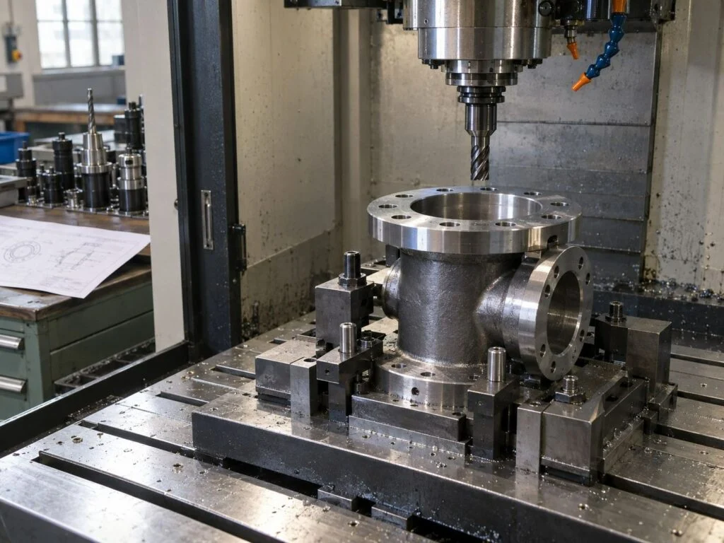
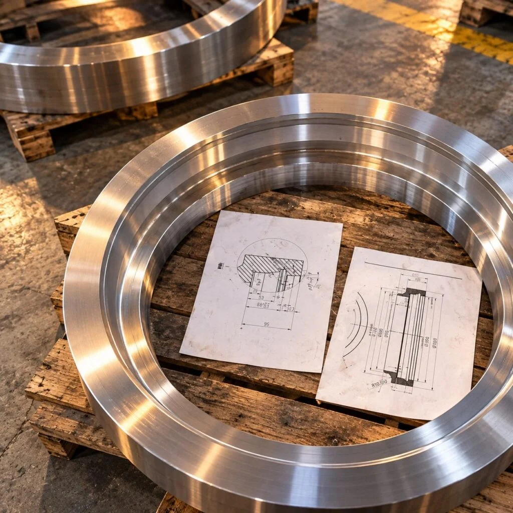
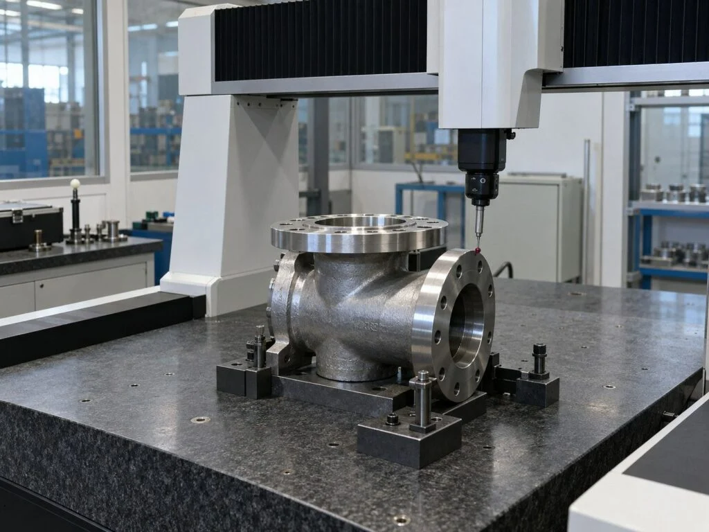
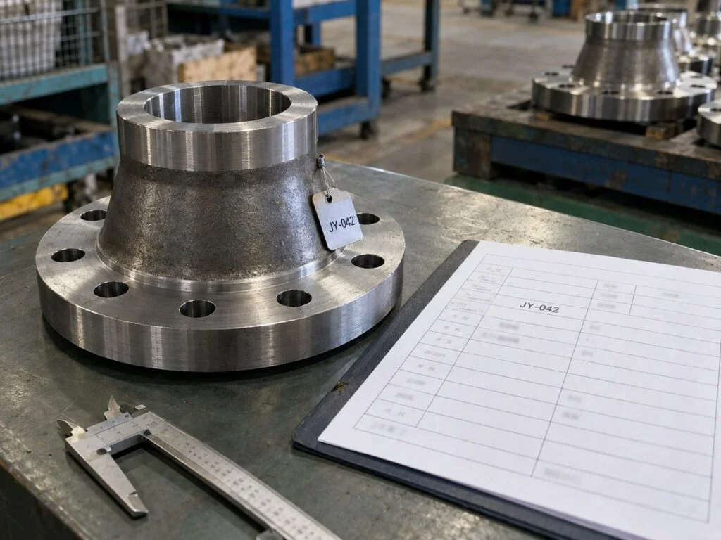
Manufacturing scope
Stage 01
Establish the drawing revision, function, material and acceptance requirements.
Custom OEM Pipe Fittings and Flanges manufactured to your drawing
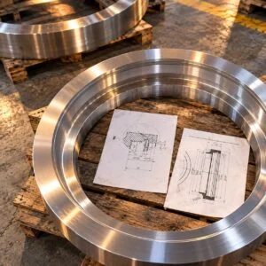
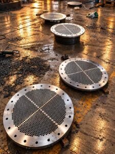
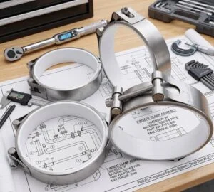
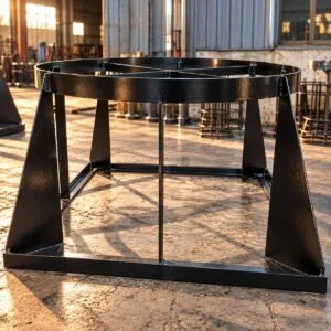
Custom manufacturing services start with a complete part definition. Specify the fitting geometry, flange interfaces, material and inspection requirements so the drawing, model and quotation describe the same component.
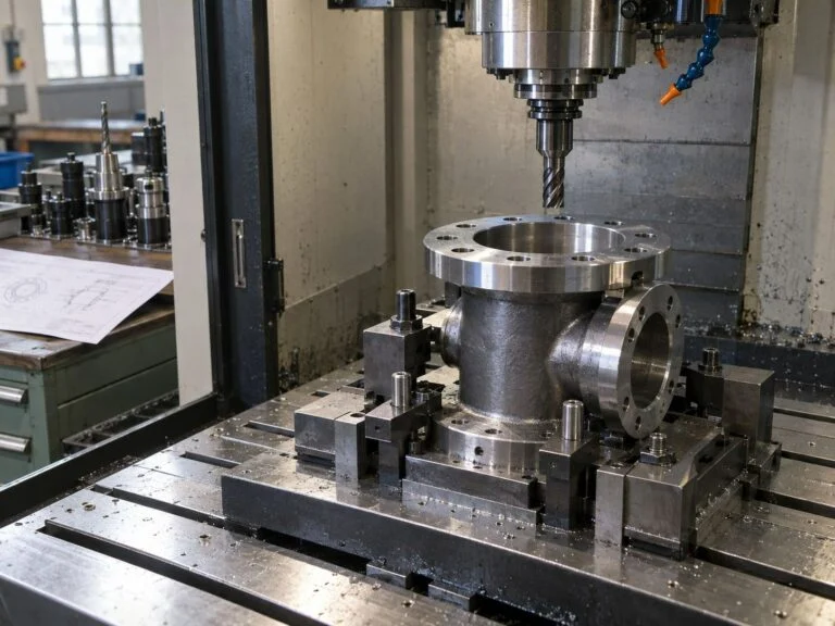
JINYI reviews enquiries for custom OEM pipe fittings and flanges, including nonstandard bores, branch connections, machined ends and flange drilling patterns. Send a revision-controlled drawing with the mating dimensions, material specification, quantity and service conditions. The technical review establishes the proposed manufacturing route, first-article requirements and inspection scope before production is agreed. Custom pipe fittings made to drawing are different from selecting a standard catalog item. Use the flanges and fittings manufacturing page for standard connection production, or send JINYI your drawing package for a nonstandard requirement.
Custom fitting and flange requirements
OEM pipe fittings
Special bores, branches, ends or drilling patterns need a drawing and an approved design basis. State any standard features that must remain interchangeable. Compare the machined ring blank and profiled ring blank when defining the starting geometry for a custom circular component.
Custom flanges
Specify bore, outside diameter, thickness, bolt circle, hole quantity, sealing face and mating connection. Identify the governing standard for any dimensions that must remain interchangeable.
Fabricated assemblies
Provide component drawings, weld details and a bill of materials. Clarify final machining after welding and which dimensions apply after surface treatment.
Replacement parts
A sample can support geometry review, but appearance does not establish material, heat treatment or service rating. Agree the reconstructed specification before manufacture.
First-article approval
Define the sample quantity, measurement report, functional checks and approval authority. A first-article release should state whether tooling or process changes require resubmission.
Material control
Specify full grade, stock form and delivery condition. Document substitutions and any sourcing restrictions before the affected material is used.
Change management
Control drawing revision, deviation approval and effectivity. Repeat orders must reference the agreed revision rather than rely on an earlier photograph or description.
Repeat-order records
Link order lines, batches and inspection records. State marking, packing and record-retention expectations in the purchase specification.
Media includes product views and representative process illustrations. Illustrated equipment and inspection arrangements do not establish an offered capability; the quotation defines the agreed manufacturing and inspection scope.
Custom Fittings & Flanges
Manufacturing Controls
OEM metal component manufacturing services work best when functional requirements become measurable acceptance criteria. Define datums before tolerances, and tolerances before inspection equipment. Review whether forging, forming, machining or welding suits the material and geometry. JINYI’s quotation should distinguish included operations, externally specified processes, tooling, first articles and production inspection. A drawing-compliant part still needs the purchaser’s approved pressure or structural design basis where applicable.
- DefinitionDrawing revision, model precedence and bill of materials
- ManufactureStock form, sequence, tooling and critical features
- AcceptanceFirst article, sampling, records and release authority
controls JINYI Engineering
Document register
List drawing numbers, revisions, models and specifications with a clear order of precedence.
Functional datums
Locate critical features from the surfaces used in assembly and inspection.
Tolerance review
Separate individual tolerances from any explicitly invoked general tolerance standard.
Stock selection
Choose material specification, product form and condition for the proposed manufacturing route.
Process sequence
Allow for heat treatment, weld distortion, finishing and machining of final interfaces.
Tooling scope
Agree fixture or tool ownership, cost, maintenance and reuse conditions in the quotation.
First article
Define measured features, sample quantity, acceptance and resubmission triggers.
Special processes
List welding, heat treatment, coating and NDE requirements with applicable qualifications.
Change control
Obtain approval for departures and record which batches or serial numbers are affected.
Repeatability
Retain the agreed route, inspection references and marking through repeat production.
Custom Fittings & Flanges: Technical Details
Ten decisions to resolve before the first part
For custom OEM pipe fittings and flanges, confirm bores, threads, sealing faces, bolt patterns and material condition against the mating assembly. The controls below connect those requirements to drawing revisions, production inspection and repeat-order acceptance.
Metal component production: workshop footage. Open video
Custom OEM Manufacturing: 6 order-control stages
This route connects technical definition to repeat-order consistency. Custom pipe fittings made to drawing require approved geometry and a suitable design basis. Tooling, sample approval, special processes and inspection should be quoted explicitly, so the first batch and later orders follow the same technical scope.
Define the part and quotation scope
Send drawing number and revision, 2D drawings, the relevant 3D model and quantity. State material, product function, service conditions and required date. Identify critical features, governing standards and certificate requirements. Clarify design responsibility, confidentiality expectations and whether the request covers prototypes, a production batch or repeat supply.
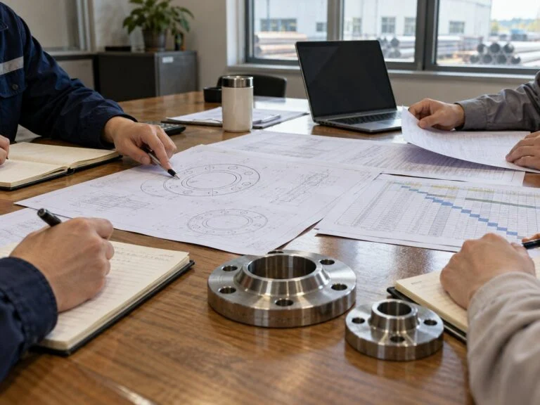
Review manufacturability and materials
Review stock form, tool access, wall transitions, drill depth, weld access and achievable inspection. Confirm the material specification and delivery condition. Propose any changes for approval before production; do not silently simplify a sealing feature or change a specified grade. Record quotation assumptions and exclusions alongside the agreed route.
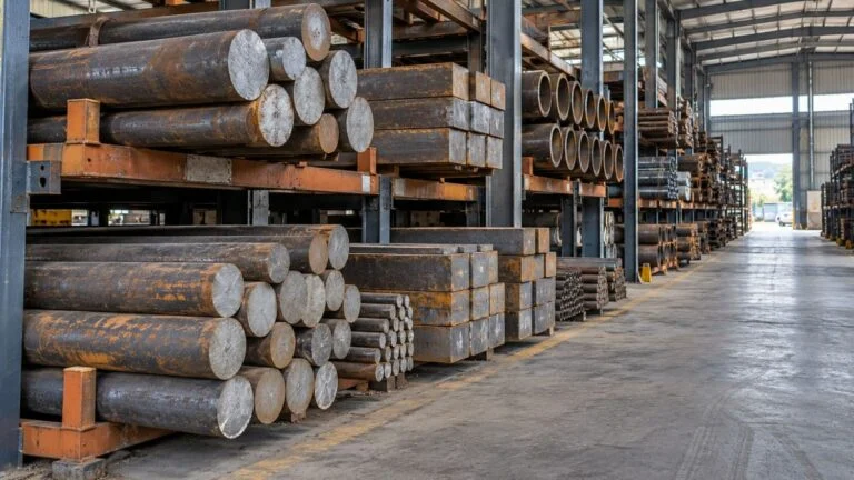
Plan tooling and first articles
Agree fixtures, tooling costs and ownership, sample quantity and the approval schedule. Define which dimensions require actual measured values and which documents accompany the sample. Establish whether the first article uses the intended production route. State what changes in tooling, material or process would trigger additional approval.
Manufacture to the controlled route
Release the agreed drawing and material to the production route. Apply the specified forming, machining, welding, heat treatment or finishing operations. Retain identification where required and inspect features before subsequent operations hide them. Record approved changes and prevent old revisions from mixing with the current order.
Measure and obtain acceptance
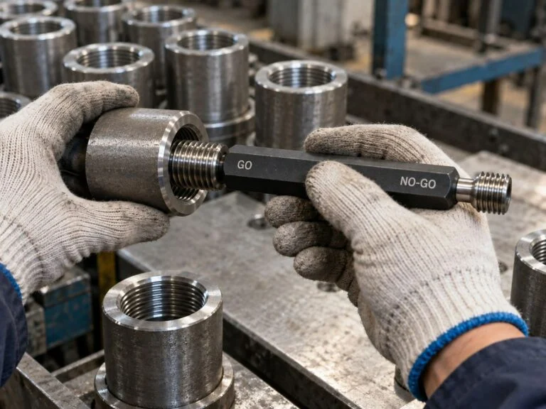
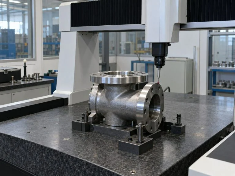
Inspect critical features using the specified datums and methods. Provide first-article or batch reports as agreed, with material and special-process records. Separate nonconforming parts and document the disposition; shipment under deviation requires the agreed approval. Confirm dimensional and functional acceptance before releasing repeat production.
Deliver and control repeat orders
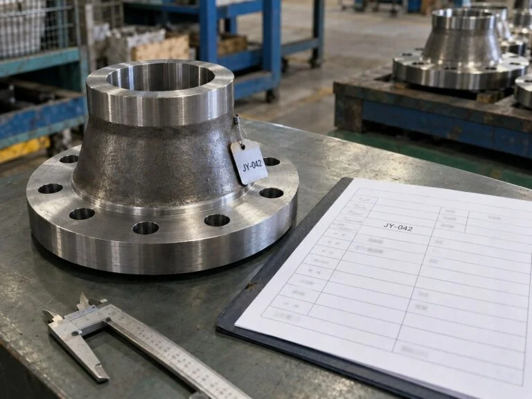
Protect machined interfaces and identify the part number, revision and batch according to the order. Match quantities and records to the packing list. For repeat orders, confirm whether the drawing, material, route or test requirements have changed. Retain the agreed technical package and reapprove changes that affect the accepted configuration.
Related products
Parts for your OEM drawing
Explore fittings, flanges and machined components to help define your drawing-based manufacturing enquiry.
View flanges & machined parts Pipe fittings & elbows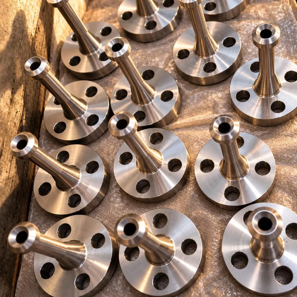
Long Weld Neck Flange
A long weld neck flange combines a drilled flange with an extended neck for a specified nozzle or connection arrangement.
- Extended welding neck
- Drilled flange interface
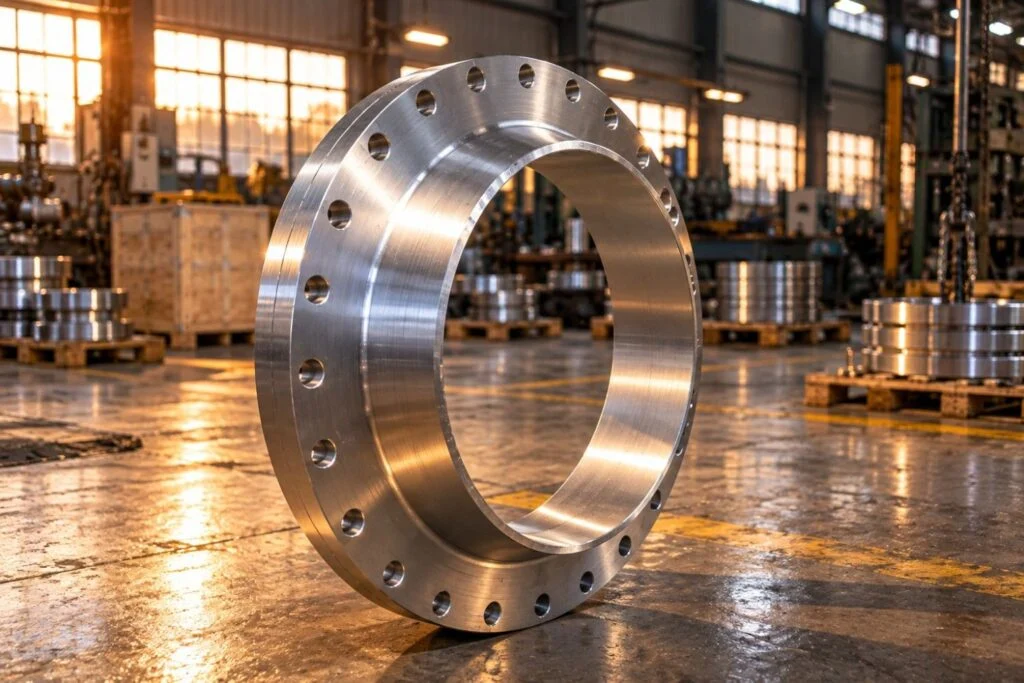
Plate Flange
A plate flange is a flat, bored ring with a drilled bolt pattern for a specified flanged connection.
- Flat bored ring
- Drilled bolt pattern
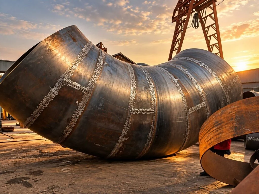
Segmented Pipe Elbow
A segmented pipe elbow forms a change of direction from joined pipe sections.
- Joined pipe segments
- Drawing-defined bend geometry
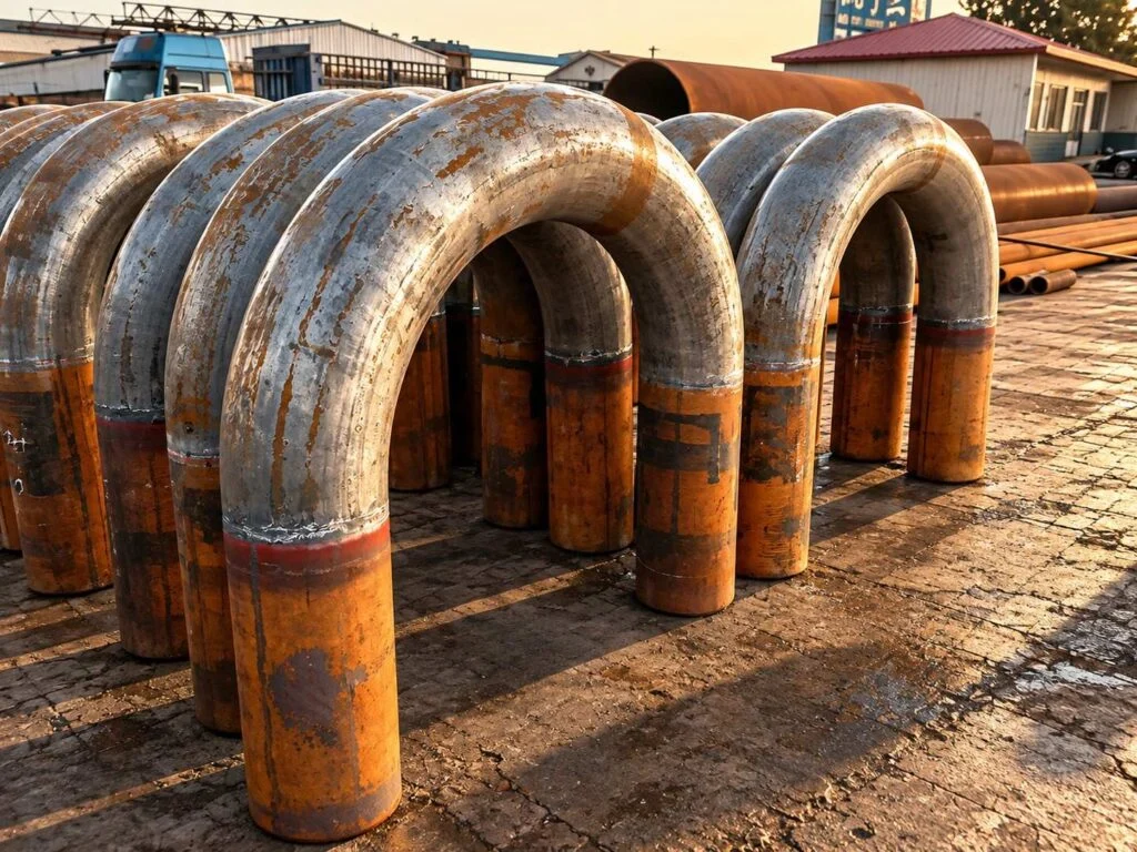
U-Shaped Pipe Bend
A U-shaped pipe bend returns a pipe route through a curved section with two straight legs.
- Curved return section
- Two straight legs
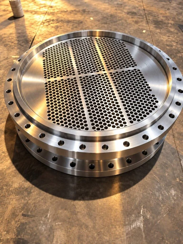
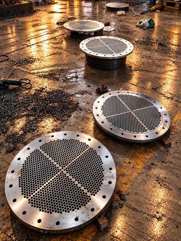
Heat Exchanger Tube Sheet
A machined plate with a controlled array of tube holes for a shell-and-tube heat exchanger.
- Controlled tube-hole array
- Machined sealing faces
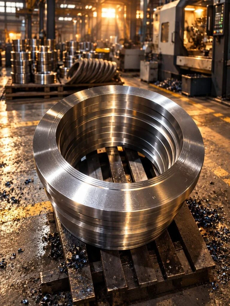
Machined Ring Blank
A machined ring blank is an annular starting component with defined outside diameter, bore and axial height.
- Annular starting component
- Defined bore and outside diameter
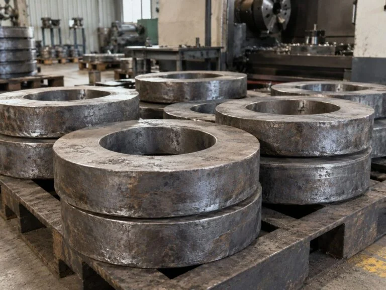
Material, form and condition. Specified before production.
For custom OEM pipe fittings and flanges, specify the full material grade, permitted product form and delivery condition. A forged flange, machined bar component and fabricated assembly may need different material specifications and manufacturing routes. Define chemical, mechanical and traceability requirements in the order, together with any heat treatment, coating, gasket or hardware specifications. Material availability and process feasibility are confirmed with the quotation.
Specify materials, process and documents for the actual order. Availability is confirmed with quotation.
Specification inputs
Custom fittings and flanges: RFQ checklist
Inputs that make a quotation comparable| Property | What to specify | Reference |
|---|---|---|
| Definition | Part number, revision, units and drawing/model precedence | Controlled technical package |
| Material | Full grade, stock form, delivery condition and traceability | Material specification |
| Geometry | Fitting bores, flange faces, bolt patterns, threads, datums and tolerances | Approved drawing |
| Processes | Forming, welding, heat treatment, finishing and qualifications | Agreed route and order scope |
| First article | Sample quantity, measurement report and approval authority | First-article plan |
| Production | Quantity, sampling, identification and deviation control | Quality and inspection plan |
| Commercial scope | Tooling, packing, delivery basis, required date and exclusions | Technical quotation |
Technical references: ASME Y14.5 dimensional tolerancing, ASTM steel material specifications. Use the drawing’s specified tolerancing system and edition consistently. Material standards distinguish product forms and applications. Referencing a standard does not establish certification or automatically approve a substitute material.
Numerical specification examples below explain how to define an enquiry. They are illustrative drawing inputs, not JINYI size, pressure, tolerance or surface-finish guarantees.
| Input | Numerical example | How to specify it |
|---|---|---|
| Bore tolerance | 50.00 ±0.05 mm | The illustrative size limits are 49.95–50.05 mm. Form, orientation and location require separate drawing controls where function needs them. |
| Bolt circle | 8 × Ø18 mm on Ø160 | Example callout: 8 equally spaced holes, each 18 mm diameter, on a 160 mm bolt circle. Define angular orientation and hole-position tolerance separately. |
| Inspection units | 0.01 mm = 10 µm | State measurement resolution and uncertainty separately. A fine display increment alone does not prove the process or instrument can meet a tolerance. |
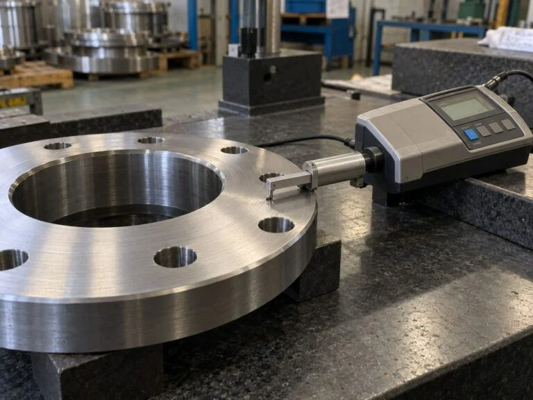
Gauging
Methods
Critical features measured from agreed datums, with revision and batch identification.
- Drawing revision and datums
- Material and delivery condition
- Critical interface dimensions
- Specified process records
- First-article and batch release
Define the inspection plan
Documents
Material records, inspection reports and packing list
Measuring equipment
Agree measuring methods, test scope and acceptance criteria for the component.
Drawing-based manufacture
OEM Metal Component Manufacturing Services
OEM metal component manufacturing services need an inspection plan tied to the drawing. For custom pipe fittings made to drawing, identify the bore, wall, end connection, thread and sealing requirements. For custom flanges, include the face geometry, bolt pattern, thickness and mating dimensions. State the pressure-design responsibility where applicable. If you supply a sample, identify the dimensions and material properties that need verification before approving a production drawing.
JINYI will review the drawing package and confirm the proposed scope, materials, first-article requirements and delivery terms. Standard product families remain covered by their dedicated pages: connectors and flexible joints, supports and casings, and tank manhole covers manufacturing.
Technical Guide & Buyer QuestionsBefore you order
Practical answers for custom pipe fitting and flange enquiries. Use these points to prepare a technical enquiry and agree acceptance. These are specification examples and buyer guidance, not customer project or testimonial claims.
Buyer guide How do I request a quote for custom OEM pipe fittings and flanges? A complete technical definition Send the part number, drawing revision, units, material specification, quantity and required date. Include fitting end connections or flange bore, thickness, sealing face and bolt pattern, together with service conditions, inspection, certificates, finishing and packing. Supply drawings and models when available and state which controls. JINYI reviews the package before confirming the manufacturing scope and quotation.
Buyer guide Can JINYI review custom flanges and nonstandard pipe fittings? Submit the interfaces and design basis Send the fitting or flange drawing, material specification and all mating details, including the connection standard where applicable. Identify pressure or structural design responsibility. Custom dimensions do not establish a pressure rating. Manufacturing feasibility, material availability, inspection and commercial terms are confirmed against the technical package before an order is accepted.
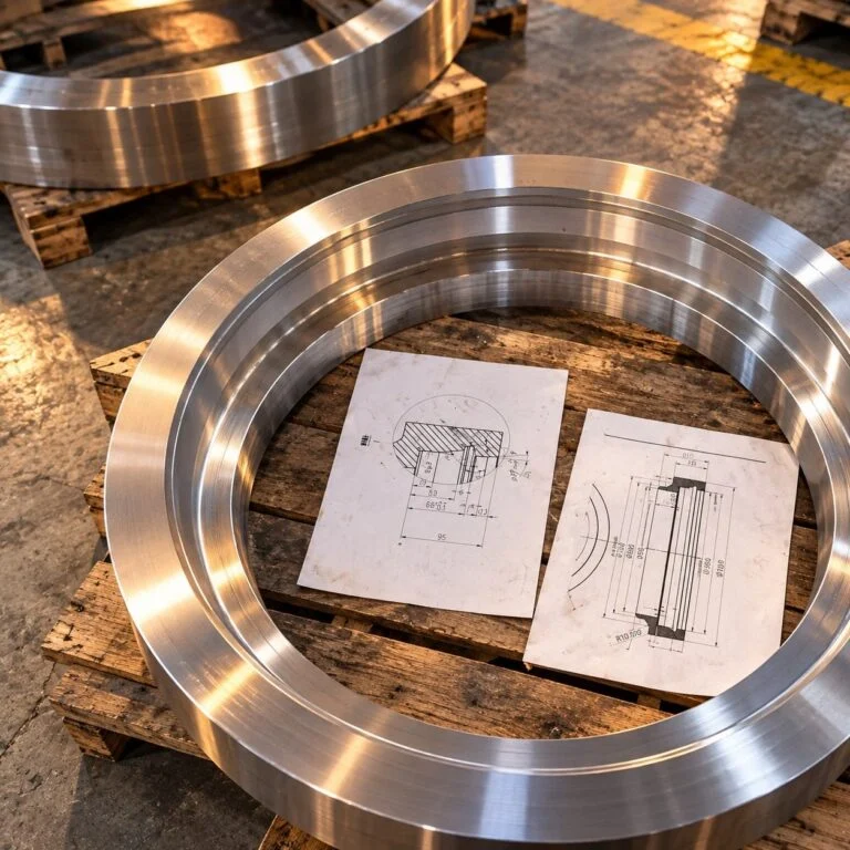 Buyer guide Is a 3D model enough to manufacture a part? Geometry does not define every requirement
 A model may omit tolerances, thread details, material condition, surface texture, coating and inspection requirements. Supply a drawing or specification that completes the definition. Agree precedence if the model and drawing disagree rather than letting production choose between them.
Buyer guide How should tolerances be assigned? Start with function and datums Identify fit, seal and alignment features and define their limits from meaningful datums. State general tolerances only where applicable. Blanket tight limits increase inspection and manufacturing effort without necessarily improving function. Do not mix tolerancing systems without an explicit design decision.
Buyer guide Can a physical sample replace a drawing? Reverse definition needs approval A sample can establish measured geometry but may be worn, modified or made from unidentified material. Agree which dimensions and properties need investigation. Approve the resulting drawing, material specification and service requirements before treating the sample as a production master.
Buyer guide What is the purpose of a first article? Confirm the agreed process output A first article demonstrates selected features and records from the proposed manufacturing route. Define sample quantity, actual-value measurements, functional checks and approval authority. It is an acceptance gate for the stated scope, not a promise that all future parts need no inspection.
Buyer guide How are material substitutions handled? Require explicit technical approval A similar trade name or chemical description is insufficient. Compare the required standard, product form, delivery condition and properties, then obtain the agreed approval before use. Record any substitution and its effect on the drawing, test requirements and affected batches.
 Buyer guide Who owns tooling and fixtures? Put the terms in the quotation
 Specify ownership, payment, maintenance, expected use, storage and access or transfer rights. Distinguish dedicated tooling from general production equipment. OEM metal component manufacturing services should identify these commercial boundaries before tooling costs are committed.
Buyer guide Does a drawing prove a pressure rating? Design and manufacture are separate No. Dimensional conformance does not establish pressure suitability for a nonstandard component. The approved design basis must address materials, loads, temperature and applicable code requirements. State who supplies and approves the necessary calculations and certification scope.
Buyer guide How are surface finishes specified? Make the requirement measurable Identify the functional surface, texture parameter and limit where required, coating system and thickness, masking and inspection method. State whether dimensions apply before or after coating. A visual description such as smooth or polished is incomplete for a controlled interface.
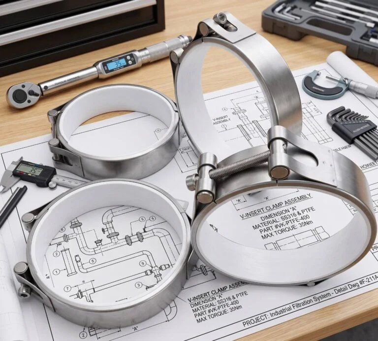 Buyer guide What changes require renewed approval? Define effectivity and resubmission
 Agree triggers such as drawing revision, material change, tooling change, manufacturing route change or altered special process. Record the affected lots and approval authority. Keep accepted deviations separate from permanent drawing changes so repeat orders do not inherit unintended departures.
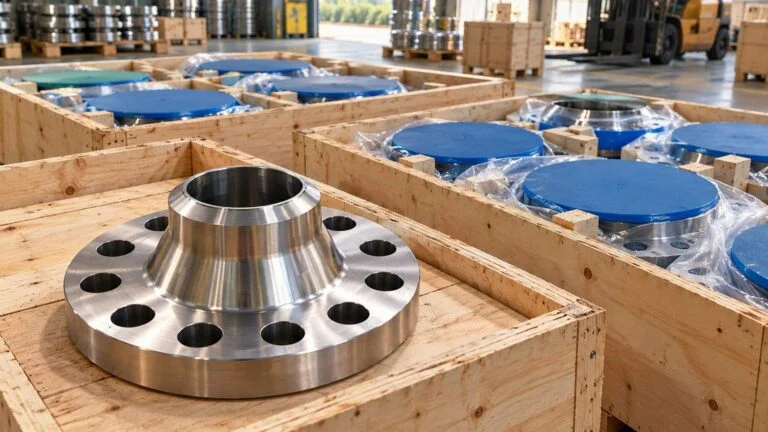 Buyer guide What supports consistent repeat orders? Retain the accepted technical package
 Reference the same drawing revision, material and route unless a change is approved. Preserve the inspection plan, part identification and acceptance records. Confirm quantity, delivery and packing again; previous commercial terms or a previous sample do not automatically define a new order.
Turn your drawing into a controlled production scope.
Ready to quote your custom fittings and flanges?
Send your fitting or flange drawing, revision, material specification and quantity. Include mating dimensions, service conditions, first-article approval and inspection requirements so JINYI can review a complete RFQ.
Get a quote Confirm the drawing, service conditions and inspection scope before production starts.
JINYI Engineering teamStart here
Request Custom OEM Pipe Fittings and Flanges
Send your fitting or flange drawing, revision, material specification and quantity. Include mating dimensions, service conditions, first-article approval and inspection requirements so JINYI can review a complete RFQ.
JINYI Pipe FittingsCangyan Road Industrial Park · Yanshan County · Cangzhou · Hebei