
Tank manhole covers manufacturing for defined opening geometry, sealing and access. Send JINYI your tank drawing, service conditions and closure requirements.
Tank Manhole Covers Manufacturing
Tank Access & Closure Assemblies
Manufacturing scope
Stage 01
Confirm clear opening, location, pressure or vacuum and the required opening direction.
Tank Manhole Covers Manufacturing around the vessel interface
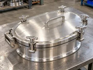
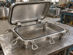
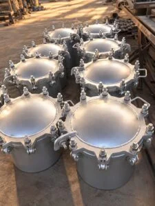
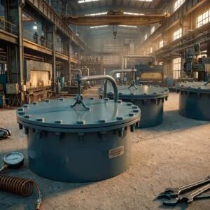
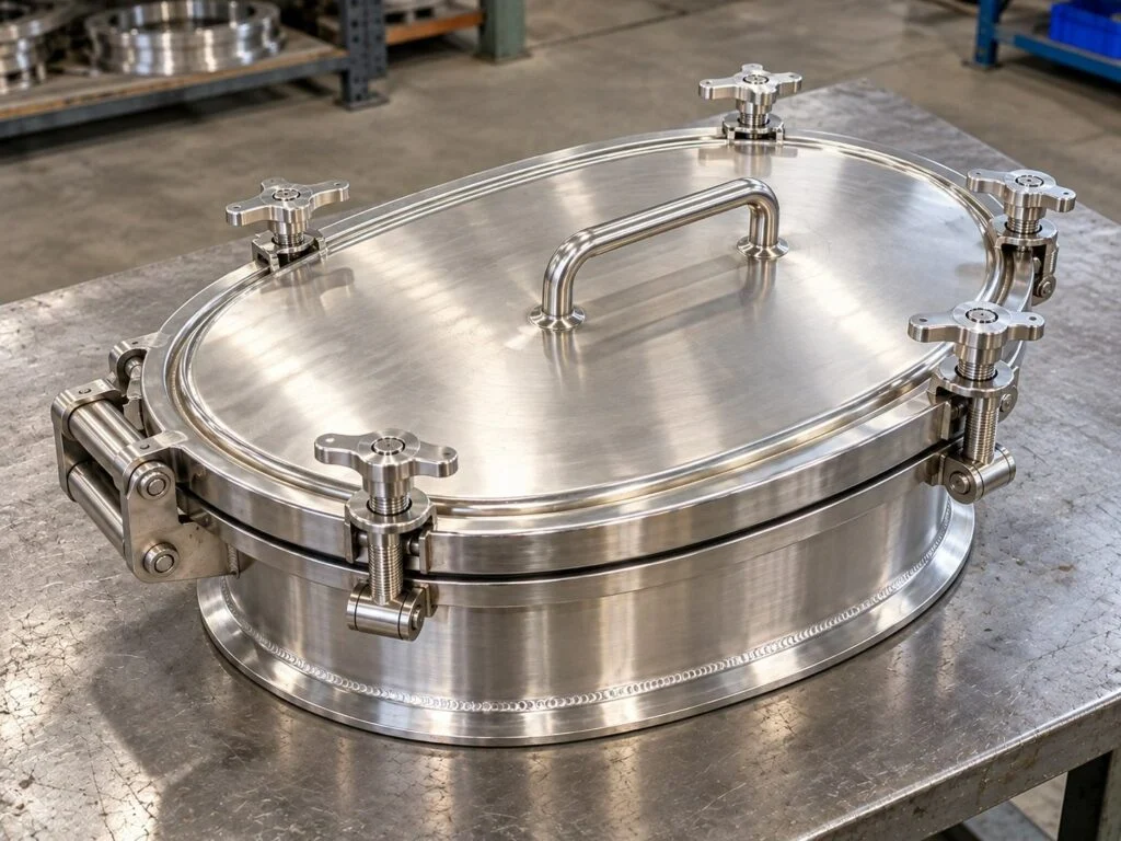
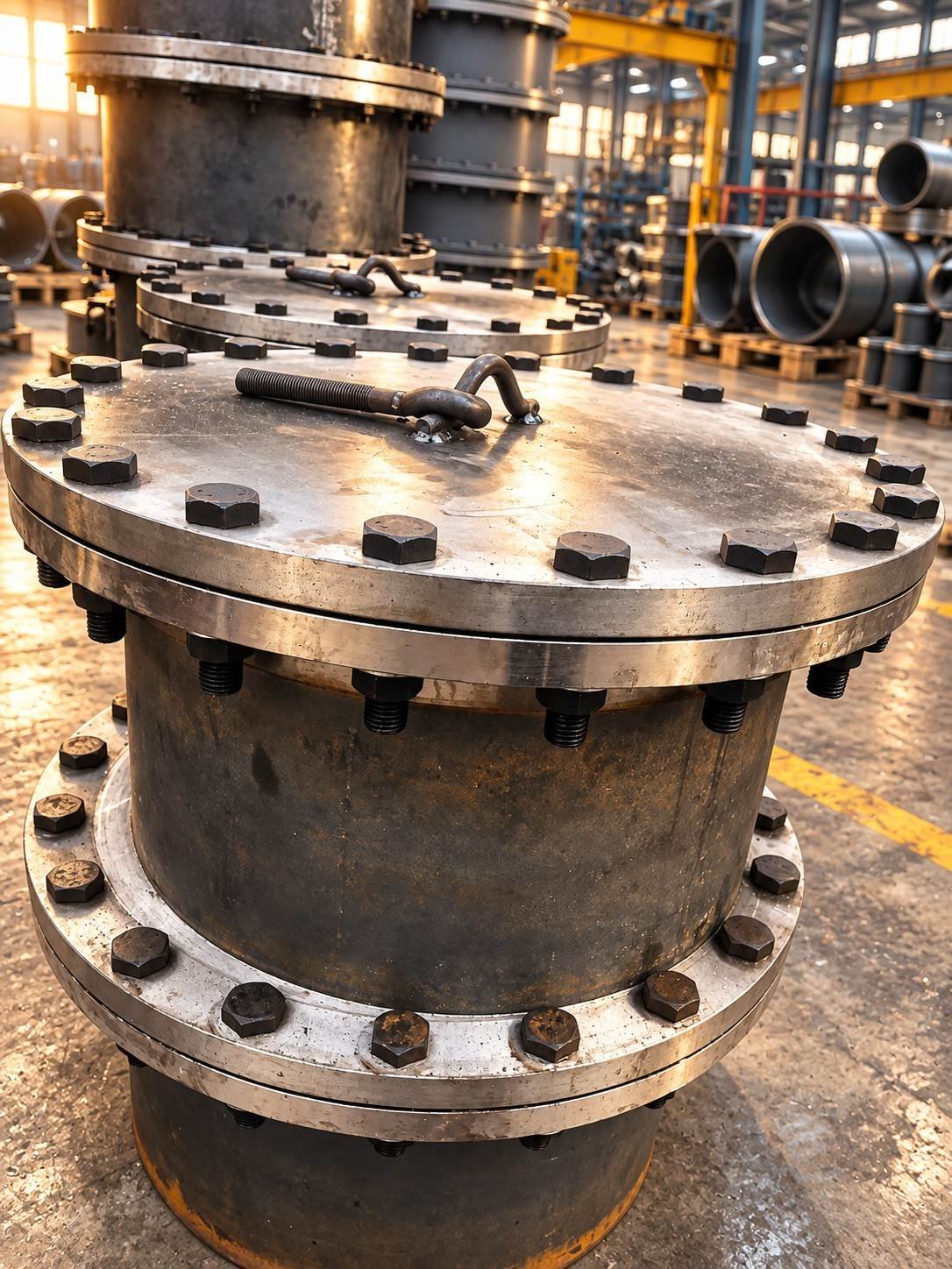
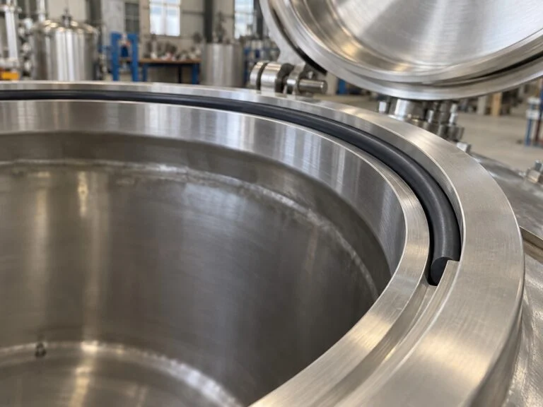
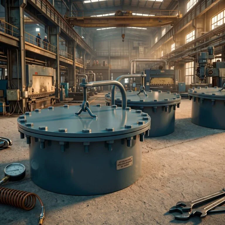
Specify tank manholes as access assemblies, with the cover, neck, seal and closing mechanism considered together. A nominal opening diameter does not establish pressure suitability or usable access. The round bolted manway and davit manway illustrate different closure and cover-handling arrangements to review against the tank drawing.
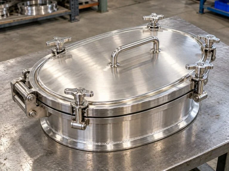
JINYI’s tank manhole covers manufacturing enquiries cover the access opening, neck or frame, cover and closure arrangement. The important manufacturing interfaces are the tank attachment, clear opening, gasket seat and operating hardware. Browse tank manhole covers for product configurations. This page explains fabrication and acceptance requirements. Material options, pressure duty, inspection and any certification scope must be confirmed for the specific order.
Define the complete access assembly
Circular tank manholes
Specify clear opening separately from neck OD, cover OD and bolt circle. State top or side entry and the required orientation of the hinge.
Oval access covers
Show major and minor clear dimensions, the insertion path and internal clearance. An inward-opening cover needs sufficient room inside the tank.
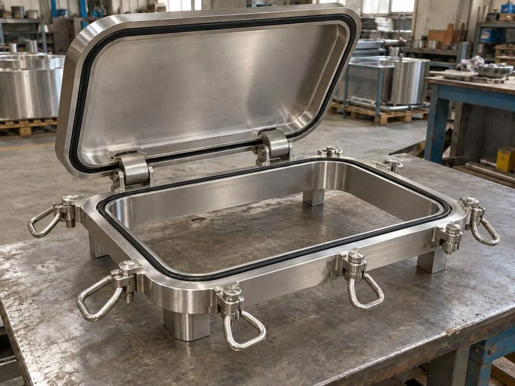
Rectangular access frames
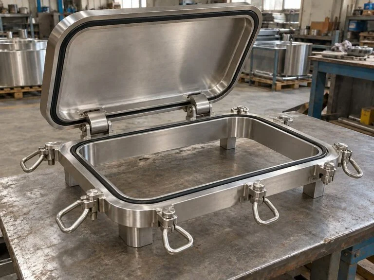
Define corner radii, frame stiffness and sealing-land geometry. Long straight sides need an appropriate closure design to maintain gasket compression.
Stainless steel manways
Specify wetted material, weld finishing, roughness and cleaning requirements. A polished appearance does not establish a hygienic or pressure certification.
Pressure and vacuum duty
Identify the vessel design basis and operating cases. Cover, neck, fasteners and seal must be assessed as an assembly for the specified duty.
Controlled closure geometry
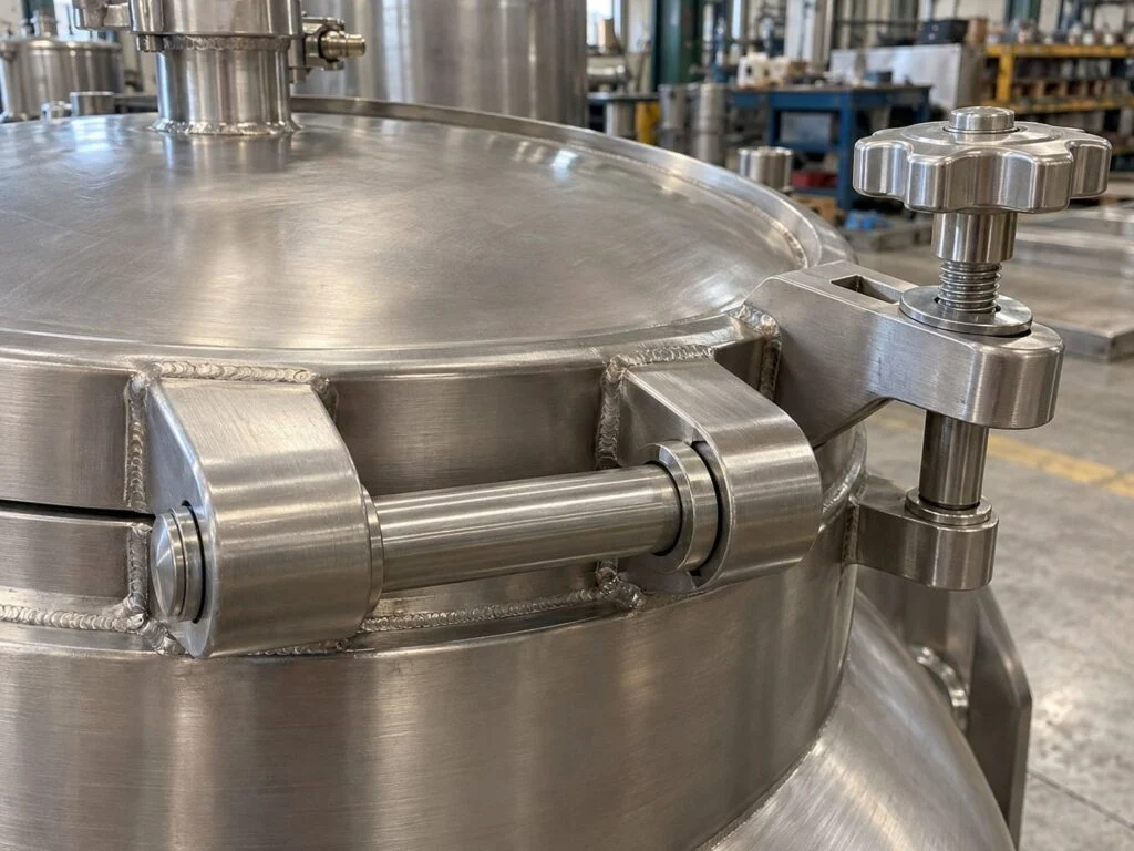
Locate hinges, swing bolts, clamps or handles to support correct seating and service access. Define replacement hardware and gasket information.
Tank attachment
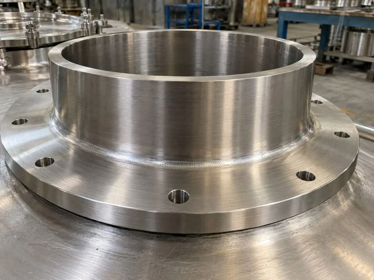
Coordinate weld preparation, neck projection, shell curvature and any reinforcement detail with the vessel designer before production.
Inspection and packing
Agree dimensions, weld examination, surface condition and any leak test. Protect gasket lands and retain matched closure components during transport.
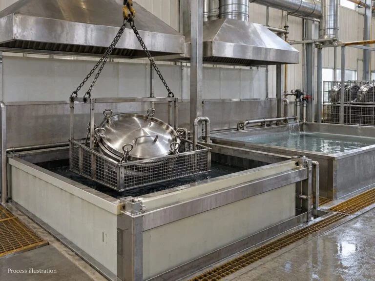
Media includes product views and representative process illustrations. Illustrated equipment and inspection arrangements do not establish an offered capability; the quotation defines the agreed manufacturing and inspection scope.
Tank Manway Fabrication
Process Controls
The tank manway cover fabrication process links forming and welding to a functional seal. Control neck roundness, cover profile, gasket-groove dimensions, seating alignment and fastener engagement. Weld shrinkage can change these relationships, so define the measurement stage and acceptance criteria. For stainless steel manways, keep material identification and surface treatment requirements separate from any pressure-vessel or hygienic approval requested by the buyer.
- AccessClear opening, hinge sweep and internal clearance
- ClosureGasket section, fasteners and seating alignment
- ServicePressure, vacuum, medium and cleaning cycle
controls JINYI Engineering
Opening geometry
Specify usable opening dimensions rather than relying on a nominal model size.
Neck preparation
Define height, wall thickness, roundness and the tank-side weld preparation.
Cover forming
Control cover thickness and profile against the approved design and forming route.
Gasket seat
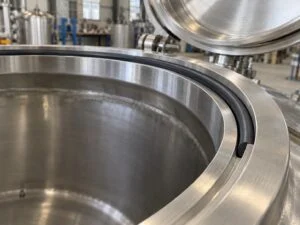
Inspect groove width, depth, radii and contact condition for the specified gasket.
Closure hardware
Confirm bolt count, thread engagement, hinge position and locking arrangement.
Weld finishing
Define weld examination and permitted blending without reducing required thickness.
Surface condition
Specify measurable roughness where required, together with the measurement locations.
Material identity
State the full material specification for wetted parts, hardware and the gasket.
Functional fit
Check opening movement, seating and hardware access on the assembled unit.
Release records
Match the approved drawing, material records, inspections and packing list.
Tank Manholes: Fabrication Details
Ten interfaces that affect access and sealing
Custom stainless steel tank manhole covers require coordinated drawings for the vessel connection and closure. The controls below make the enquiry precise without assuming a standard pressure rating, universal roughness value or unverified sanitary approval.
Hinged access covers: workshop product footage. Open video
Tank Manhole Covers Manufacturing: 6 fabrication stages
Use the tank manway cover fabrication process to define responsibility at every interface. The tank designer establishes the required duty and attachment design. The component quotation should identify materials, geometry, inspections and documents, including any approval that must be independently verified.
Review access and vessel duty
Provide the tank drawing, opening position and clear access dimensions. State normal and design pressure, vacuum, temperature, stored medium and cleaning cycle. Identify inward, outward or sideways opening and available hinge clearance. Confirm the vessel design basis and which party approves pressure-boundary and reinforcement calculations.

Select materials and gasket
Specify the full material designation for the neck, cover, fasteners and wetted hardware. Evaluate gasket compatibility with both process and cleaning fluids. State traceability and document requirements. A stainless grade name alone does not establish suitability for chloride exposure, a cleaning regime or a particular regulatory approval.
Form neck and cover components
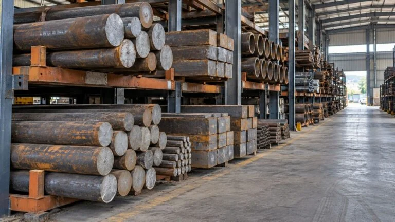
Cut and form the specified plate or other permitted starting stock. Control neck geometry, cover profile and any frame corner radii. Preserve the required finished thickness and machining allowance. Mark material identity through the route where traceability is required, and inspect features that will become inaccessible after assembly.

Weld, machine and fit hardware
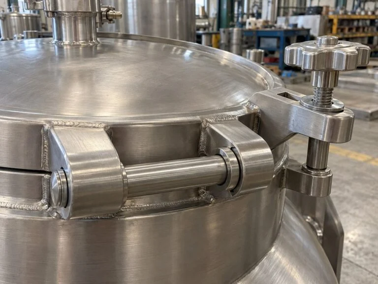
Complete the specified fabrication welds and control distortion. Prepare gasket lands or grooves, drill the required patterns and fit hinges, clamps or swing bolts. Verify the cover seats without forcing and that hardware can be operated in the installed position. Coordinate tank-side weld preparation with the vessel fabrication detail.
Finish and verify acceptance
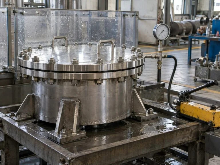
Check clear opening, neck dimensions, cover fit, weld condition and surface requirements. Perform the ordered examinations and agreed leak or pressure test using a documented procedure. If passivation or measured roughness is required, define the records and acceptance criteria. Verify claimed approvals against the actual supplied configuration.
Pack and release the assembly
Protect gasket seats, polished surfaces and projecting hardware from transport damage. Identify the gasket and matched closure parts, and include ordered spares. Match the marking and packing list to the approved drawing. Supply agreed material and inspection records plus the instructions needed for installation and maintenance.
Related products
Manways & tank covers
Explore tank access closures and related cover components, from bolted manways to formed tank heads.
View tank covers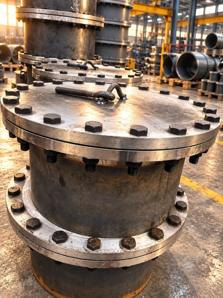
Round Bolted Manway
A round bolted manway provides a circular access opening closed by a bolted cover.
- Circular access opening
- Bolted cover
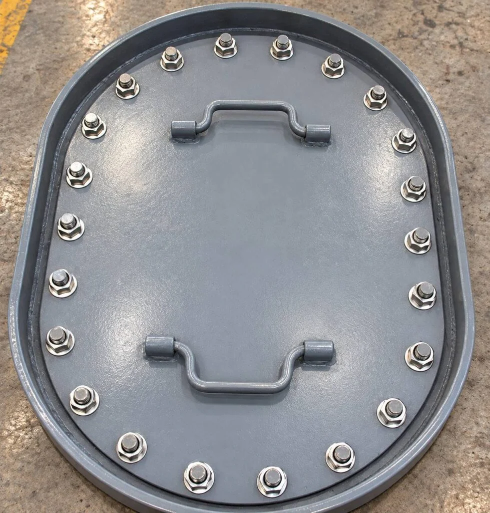
Oval Bolted Manway
An oval bolted manway provides an oval access opening with a bolted cover arrangement.
- Oval access opening
- Bolted closure
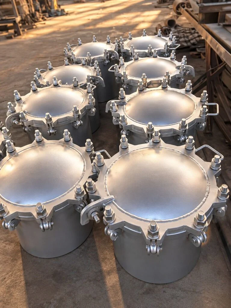
Swing Bolt Manway
A swing bolt manway uses perimeter swing-bolt hardware to secure the specified access cover.
- Swing-bolt hardware
- Removable access cover
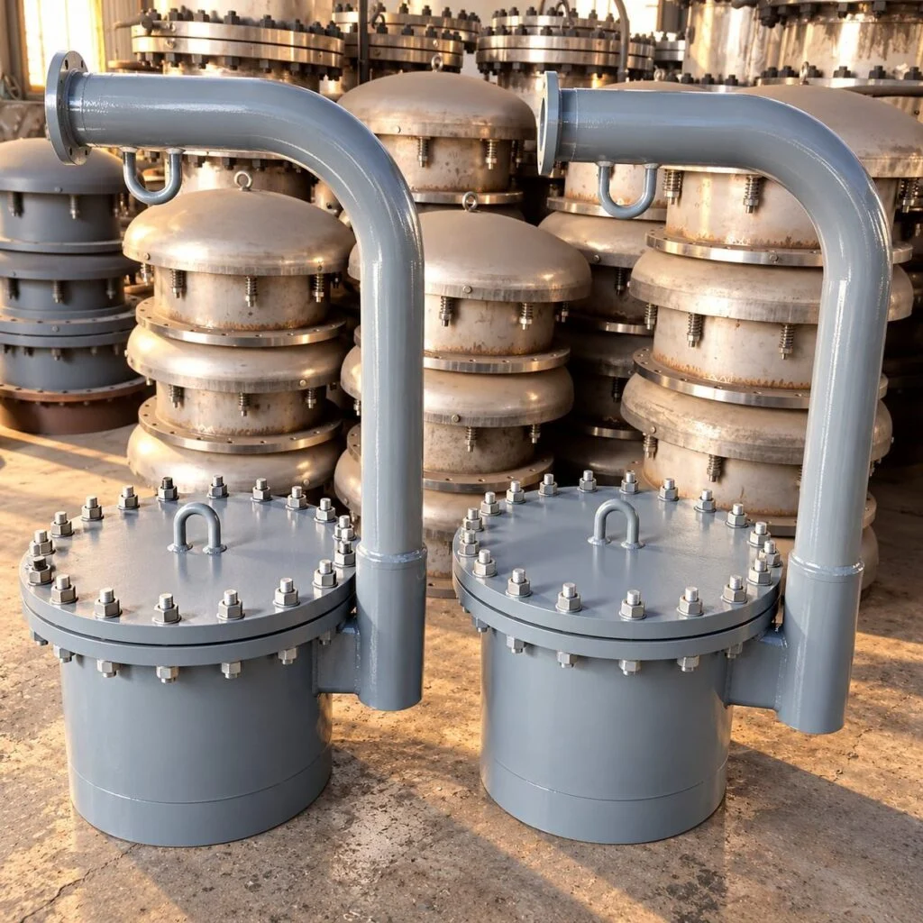
Davit Manway
A davit manway combines a tank access closure with a specified arm arrangement for handling the cover.
- Davit-assisted handling
- Tank access closure
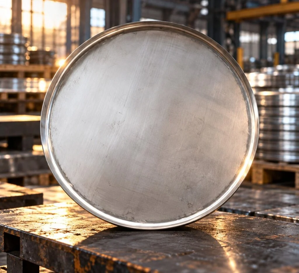
Flat Circular Tank Cover
A flat circular tank cover closes a circular opening using a flat plate profile and a specified attachment or sealing detail.
- Flat plate profile
- Circular opening closure
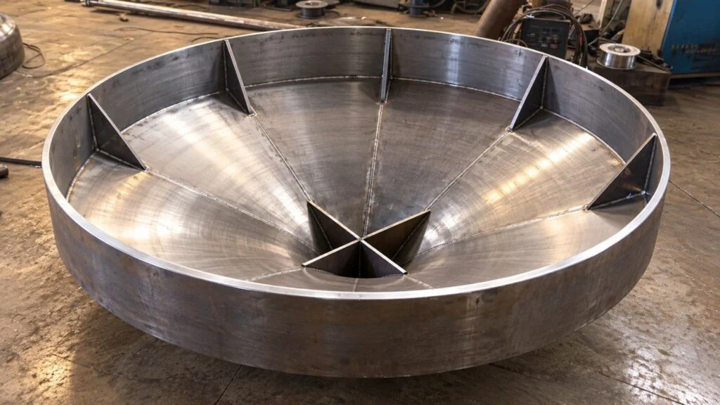
Tank Head with Central Opening
A tank head with a central opening integrates a formed closure with a drawing-defined passage for an outlet, nozzle or other connection.
- Formed tank closure
- Drawing-defined opening
Stainless steel and gasket selection. Defined by the tank service.
Common enquiry options include 304 or 316L stainless construction and application-specific gasket compounds. Specify the governing material standard and delivery condition, not just an informal grade name. Review product contact, cleaning chemicals, temperature and corrosion exposure. Pressure or hygienic certification must be checked separately for the actual assembly.
Specify materials, process and documents for the actual order. Availability is confirmed with quotation.
Specification inputs
Tank manhole fabrication specification
Define the assembly and its interfaces| Property | What to specify | Reference |
|---|---|---|
| Opening | Clear diameter or major/minor dimensions in mm; access direction | Tank layout |
| Neck and frame | Height, thickness, profile, tank attachment and reinforcement interface | Vessel and component drawings |
| Cover and closure | Profile, fastener pattern, hinge orientation and operating clearance | Approved closure design |
| Service duty | Design pressure, vacuum, temperature, medium and cleaning conditions | Vessel design basis |
| Seal | Compound, cross-section, groove details and compatibility | Gasket specification |
| Surface | Weld finish, measurable roughness where required and treatment | Process finish specification |
| Acceptance | Dimensions, examination, agreed test and certificate scope | Order-specific ITP |
Technical references: Tank access and pressure configurations, ASTM A967 passivation scope, ASTM A380 cleaning and treatment scope. Tank-cover designs differ by pressure duty, opening arrangement and service. ASTM surface-treatment references describe processes; citing them does not establish pressure or hygienic certification of a JINYI assembly.
Numerical specification examples below explain how to define an enquiry. They are illustrative drawing inputs, not JINYI size, pressure, tolerance or surface-finish guarantees.
| Input | Numerical example | How to specify it |
|---|---|---|
| Clear opening | 450 × 350 mm | Example oval access dimensions are the usable major and minor axes. Specify these separately from cover, flange and neck outside dimensions. |
| Neck projection | 150 ±2 mm | An illustrative projection callout gives limits of 148–152 mm. Define the vessel reference surface and whether the dimension applies after welding. |
| Surface finish | Ra 0.8 µm example | A specified roughness limit must name the measured surface, evaluation conditions and agreed acceptance method. This example is not a universal hygiene requirement or a confirmed JINYI finish. |
Gauging
Methods
Opening, neck, gasket seat and closure hardware checked against the assembly drawing.
- Clear opening and neck geometry
- Gasket seat and cover fit
- Hinge and fastener operation
- Weld and surface condition
- Identification and ordered reports
Define the inspection plan
Documents
Material records, inspection reports and packing list
Measuring equipment
Agree measuring methods, test scope and acceptance criteria for the component.
Drawing-based manufacture
Custom Stainless Steel Tank Manhole Covers
For a custom assembly, provide the tank-side connection and clear opening together with the cover, gasket and closure details. Highlight required datums, sealing tolerances and surface measurements. State the medium, pressure, vacuum and cleaning conditions so a quotation covers the actual duty rather than a visually similar access hatch.
JINYI will review the requested fabrication scope, material availability, inspection plan and commercial terms. Identify the approval authority for pressure design and any required third-party certification before manufacture. For broader drawing-controlled assemblies, see custom manufacturing and OEM.
Technical Guide & Buyer QuestionsBefore you order
Practical answers for tank manhole covers manufacturing. Use these points to prepare a technical enquiry and agree acceptance. These are specification examples and buyer guidance, not customer project or testimonial claims.
Buyer guide What starts a tank manhole manufacturing enquiry? The tank interface and service Provide the tank drawing, clear opening, location, pressure and vacuum duty, temperature and medium. Add material, gasket, opening direction and surface requirements. Tank manhole covers manufacturing needs an assembly specification rather than a cover diameter alone.
 Buyer guide Is nominal diameter the usable opening? State the clear dimension
 Not necessarily. The neck wall, gasket seat or internal cover geometry can reduce access. Specify the required clear opening and compare it with the finished assembly drawing. Include any internal obstruction and the space needed to move the cover.
Buyer guide Can an atmospheric cover serve a pressure tank? Confirm the design duty Do not infer pressure suitability from stainless construction or cover thickness. Positive pressure, vacuum and temperature must be assessed for the complete closure and tank attachment. Obtain the documented rating and required approval for the exact assembly.
Buyer guide How are 304 and 316L selected? Use service-specific corrosion review Consider the process fluid, chlorides, cleaning chemicals, temperature and fabrication condition. Neither grade is universally corrosion-proof. Specify the full material standard and any required verification. Do not substitute one grade solely because a component looks the same.
 Buyer guide Which gasket information is required? Compound and interface details
 State compound, cross-section, groove arrangement, medium and cleaning conditions. Temperature and compression requirements depend on the actual formulation and closure design. A general food-grade description does not replace the documentation required for the intended contact application.
 Buyer guide What does the fabrication process control? Geometry through assembly
 The tank manway cover fabrication process controls neck and cover shape, weld distortion, seal-seat geometry and operating hardware. Define inspection points before finishing or assembly hides critical features. Functional opening and seating checks should address the installed orientation.
Buyer guide Does a polished surface prove hygienic design? Appearance is insufficient No. Cleanability also depends on crevices, gasket placement, weld quality, drainage and access. Specify measurable roughness where required and the locations to inspect. Any hygienic approval must apply to the actual model and configuration supplied.
Buyer guide What does passivation establish? A defined surface-treatment scope Passivation is a specified chemical treatment with its own acceptance requirements; it is not a pressure test or a substitute for removing gross fabrication defects. Agree the applicable procedure and verification. Cleaning, descaling and polishing are distinct operations.
 Buyer guide How should a hinge be specified? Check the real opening envelope
 Show orientation, sweep, nearby pipework and maintenance clearance. State whether the cover is removable, captive or needs lifting assistance. Ensure the chosen arrangement allows the gasket to seat correctly and the fasteners to be operated after installation.
Buyer guide Which tests should be requested? Define the tested boundary List dimensional checks, weld examination, surface measurements and any leak or pressure test. Specify procedure and acceptance criteria, including whether the test covers the component or the completed vessel. A component report must not be presented as certification of the entire tank.
Buyer guide Can a cover be opened while the tank is pressurized? Follow the approved operating procedure The tank must be isolated and its pressure state verified before the closure is opened, following the equipment instructions and site procedure. Specify the necessary closure safeguards for the design. Manufacturing information on this page is not an operating authorization.
Buyer guide What belongs in the delivery package? Identification and maintainability Request the approved drawing, material records, inspection reports and assembly instructions within the agreed scope. Identify the replacement gasket and hardware. Protect sealing lands and finished surfaces so the receiving inspection can distinguish transport damage from fabrication issues.
Specify access, sealing and service together.
Ready to send your tank opening drawing?
Send the clear opening, neck dimensions, material, pressure or vacuum, gasket and finish requirements. JINYI will review the assembly and quotation scope.
Get a quote Confirm the drawing, service conditions and inspection scope before production starts.
JINYI Engineering teamStart here
Start Your Tank Manhole Covers Manufacturing Enquiry
Send the clear opening, neck dimensions, material, pressure or vacuum, gasket and finish requirements. JINYI will review the assembly and quotation scope.
JINYI Pipe FittingsCangyan Road Industrial Park · Yanshan County · Cangzhou · Hebei