

Pipe OD · Wall Detail · Seal
Waterproof Casings & Sleeves
Waterproof casings and sleeves coordinated with pipe diameter, concrete-wall details, water pressure and the penetration sealing system.
Specification basis
Confirm the applicable drawing and requirements
Inspection scope
Defined against the approved order
 Category Waterproof Casings & Sleeves Pipe OD · Wall Detail · Seal
 Divide by 2 for radial gap
ID − OD
Specification input
State level and pressure
Head
Specification input
About this range
Seal the pipe and the wall interface
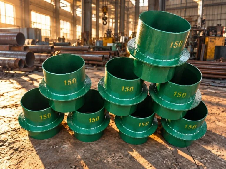
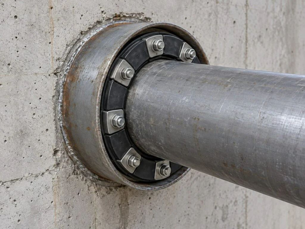
Waterproof casings form a controlled penetration through a wall or slab so the carrier pipe and the surrounding structure can be detailed correctly. JINYI lists rigid wall sleeves and flexible waterproof sleeves. The casing-to-concrete interface and the pipe-to-casing annulus are separate potential water paths; both need an approved sealing detail. Select waterproof pipe sleeves using actual pipe outside diameter, sleeve inside diameter, wall thickness and water exposure, rather than choosing the carrier pipe’s nominal size alone.
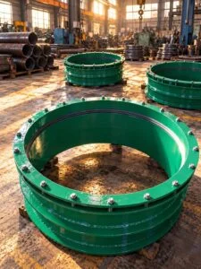
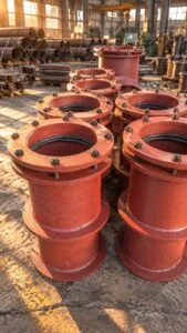
- Rigid waterproof casings for concrete walls are normally coordinated with the cast-in wall detail. Confirm the sleeve barrel, waterstop ring and sealing treatment shown on the drawing.
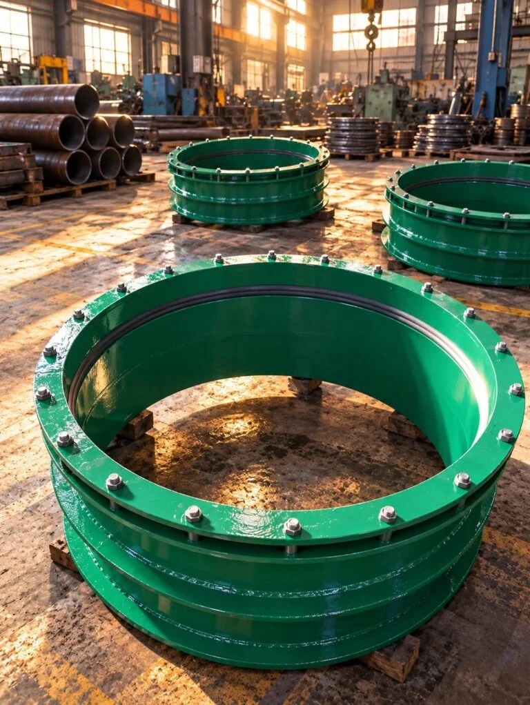
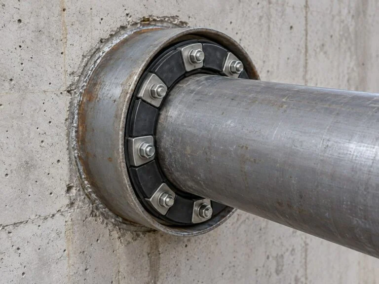
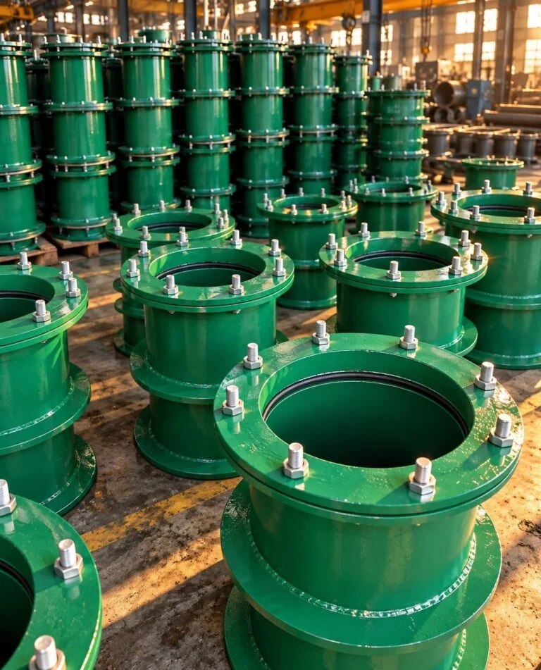
- Flexible waterproof sleeves for pipe penetrations include a sealing assembly whose allowable movement must be confirmed. Flexible is not a statement of unlimited settlement capacity.
- Calculate radial annular space as (sleeve ID − pipe OD) / 2. For example, a 200 mm bore around a 114.3 mm pipe gives 42.85 mm radial space; this is a sizing illustration only.
- Specify wall thickness and any projection on each face. Include waterproof membrane interfaces, reinforcement clearance and access to the gland or fasteners.
- State the water head and direction of pressure. Internal carrier-pipe pressure is a different condition from groundwater pressure acting across the wall penetration.
- Identify the drawing reference and type when using 02S404 details. Confirm the project’s selected configuration instead of treating every sleeve as interchangeable.
Featured waterproof casings & sleeves
Selected waterproof casings & sleeves for project enquiries. Compare the connection, installation and specification details, then request a quotation for your required configuration.
See the full catalogueA flexible waterproof sleeve uses a specified housing and sealing assembly around a pipe penetration. Specify dimensions, material and service conditions for a Jinyi quotation.
Flexible Waterproof Sleeve
View detailsA rigid wall sleeve creates a defined pipe passage through a wall and can incorporate a puddle flange in the specified concrete penetration detail. Specify dimensions,…
Rigid Wall Sleeve
View detailsWaterproof Casings & Sleeves catalogue
Browse 2 products in this category. Search the range or compare the available enquiry options. Final materials, dimensions and ratings are confirmed against the selected product and your specification.
Showing 1–2 of 2 products
A flexible waterproof sleeve uses a specified housing and sealing assembly around a pipe penetration. Specify dimensions, material and service conditions for a Jinyi quotation.
Flexible Waterproof Sleeve
View detailsA rigid wall sleeve creates a defined pipe passage through a wall and can incorporate a puddle flange in the specified concrete penetration detail. Specify dimensions,…
Rigid Wall Sleeve
View detailsProduct capabilities
Sleeve geometry and penetration sealing
Waterproof casings should be scheduled alongside the civil and piping drawings. A rigid sleeve provides a passage and a specified wall interface; the complete waterproof detail also needs the correct annular seal. A flexible assembly introduces a gland or seal arrangement with its own dimensions and limits. For a rough opening or core-drilled retrofit, identify the bore condition and the selected sealing system before specifying a casing. Product selection must account for pipe movement without transferring unapproved loads into the wall or seal.
- Wall thickness: Concrete plus finishes
- Waterstop: Drawing and ring location
- Water head: Level and pressure direction
- Movement: Axial / lateral requirement
Specification
Fit calculation
ID − OD
Divide by 2 for radial gap
Water exposure
Head
State level and pressure
Four checks before specifying waterproof casings
Use these checks to define the waterproof casings assembly before comparing prices. Record the decision against the drawing revision and obtain confirmation of the proposed model’s limits.
- Measure the penetration Record carrier-pipe OD, sleeve bore, wall thickness, pipe angle and required projection.
- Choose the wall detail Identify cast-in sleeve or retrofit opening, waterstop arrangement and membrane connection.
- Specify the seal duty Define water head, movement, fluid exposure, pipe surface and seal-material requirements.
- Coordinate installation Confirm reinforcement clearance, fixing position, protection during concrete work and access for inspection.
Dimensions and service conditions should be agreed before ordering.
Flexible waterproof sleeves for pipe penetrations
For waterproof casings, send actual pipe OD, material, sleeve bore, wall thickness, required length and the wall-penetration drawing. Include water head, pressure direction, expected movement, waterstop and membrane details, coating, seal requirements and quantities.
- Cast-in sleeves Provide wall and reinforcement drawings, sleeve length, waterstop-ring position and installation tolerances.
- Flexible gland assemblies State pipe OD, sealing width, gland dimensions, bolt access and the movement that the detail must permit.
- Corrosion protection Identify buried, immersed or exposed conditions, coating specification and stainless grades where required.
- Retrofit penetrations Supply the measured opening, bore surface, pipe eccentricity and the approved repair or seal detail.
Send drawings and the item schedule with your enquiry.
Inspection requirements for waterproof casings
Waterproof sleeve inspection should address both manufactured dimensions and installation interfaces. A casing alone cannot establish the watertightness of the completed wall. Agree how the sleeve, concrete interface, annular seal and installed pipe will be inspected and tested.
Inspection checklist
Specify in the order- Barrel geometryInside diameter, wall thickness, length and end squareness.
- Waterstop detailRing diameter, thickness, position and specified weld condition.
- Gland and sealComponent sizes, compound identification and mating surfaces.
- Coating and protectionSurface preparation, coverage and sealing-area cleanliness.
- Installed interfacePosition, annular gap, access and the agreed watertightness test.
Order documentation
Scope to confirm- Approved drawingDimensions, revision and acceptance criteria
- Material recordSpecify traceability and document type
- Inspection reportAgree measured items and test scope
- Project approvalsConfirm any required certificates before ordering
Quality
Inspection · gauging
Standards · documents
Review checkpoints
Document control
Six inspection planning steps
A purchase-order checklist- 1
Drawing review
Confirm the specification, revision and the selected waterproof casings configuration.
- 2
Barrel geometry
Inside diameter, wall thickness, length and end squareness.
- 3
Waterstop detail
Ring diameter, thickness, position and specified weld condition.
- 4
Gland and seal
Component sizes, compound identification and mating surfaces.
- 5
Coating and protection
Surface preparation, coverage and sealing-area cleanliness.
- 6
Installed interface
Position, annular gap, access and the agreed watertightness test.
Applications and specification priorities
Common application contexts for waterproof casings. Each installation needs a service-specific selection; the entries below describe engineering priorities, not customer projects or approvals.



Technical selection and common questions
02S404 official drawing catalogue
Read the reference scope
Confirm applicability to your selected designPipe OD and wall-bore sealing interfaces
Read the reference scope
Confirm applicability to your selected designJINYI technical help
Read the reference scope
Confirm applicability to your selected design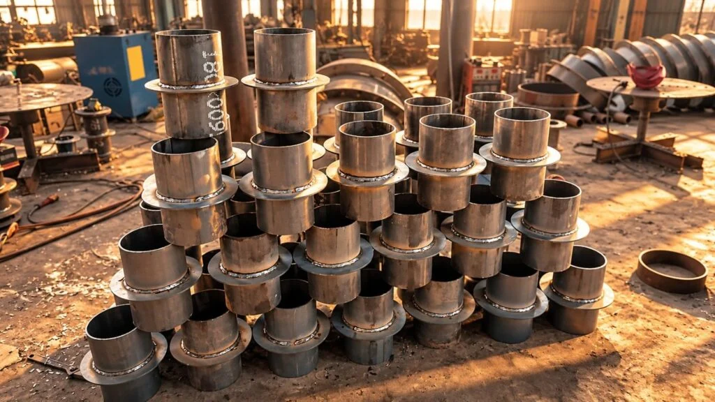
Dimension schedule
Record these fields on a drawing or item schedule. Each quotation for waterproof casings should identify the proposed configuration and any departure from the specified interface.
Discuss your specification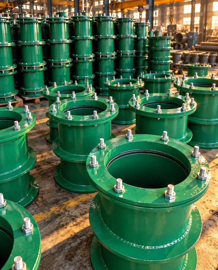
Service and installation
Include these conditions with the waterproof casings enquiry. A useful comparison checks technical compliance, inspection scope and installation requirements before comparing unit price.
Discuss your specificationQ&AAnswers for waterproof casings
Selection questions
Does DN100 mean the sleeve bore is 100 mm?
Not necessarily. DN may describe the carrier-pipe designation in a sleeve schedule. Verify the actual pipe OD and the sleeve drawing’s bore dimensions before ordering.
Is a plain wall sleeve automatically waterproof?
No. Waterproofing depends on the complete wall interface and annular sealing detail. Confirm the waterstop arrangement, sealing system and installation workmanship.
Need help with a specific drawing? Include the service conditions in your enquiry.
Discuss your specificationQ&AAnswers for waterproof casings
Installation questions
Can a flexible sleeve absorb building settlement?
Only within the movement range established for the selected assembly and civil detail. Provide the predicted displacement and direction for engineering review.
Can the same sleeve be used after concrete is cast?
A cast-in sleeve detail and a retrofit penetration are different installations. Provide the existing bore dimensions and wall condition so a suitable retrofit sealing detail can be selected.
Need help with a specific drawing? Include the service conditions in your enquiry.
Discuss your specificationRelated products for your assembly
Explore complementary products from other JINYI categories. Check each product’s dimensions and connection requirements against your assembly drawing.
See the full catalogue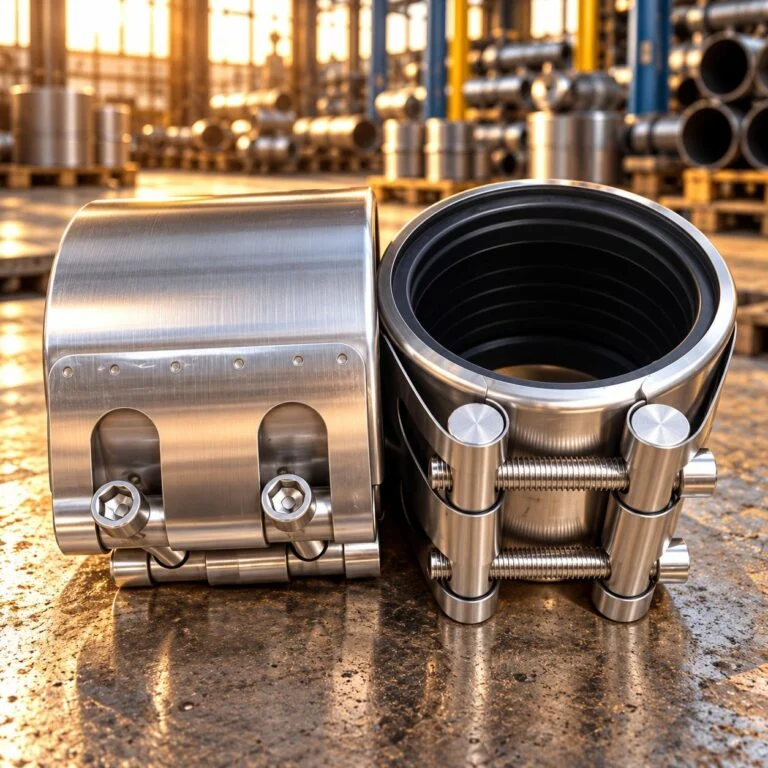
- Nominal size
- DN100
- Pipe outside diameter
- 114.3 mm
- Pressure options
- 1.0 / 1.6 / 2.5 MPa
- Housing arrangement
- 2-piece
Pipe Repair Coupling
View details
- Nominal size
- DN80
- Pressure designation
- PN16
- Pipe outside diameter
- 88.9 mm
- Flange outside diameter
- 200 mm
Plate Flange
View details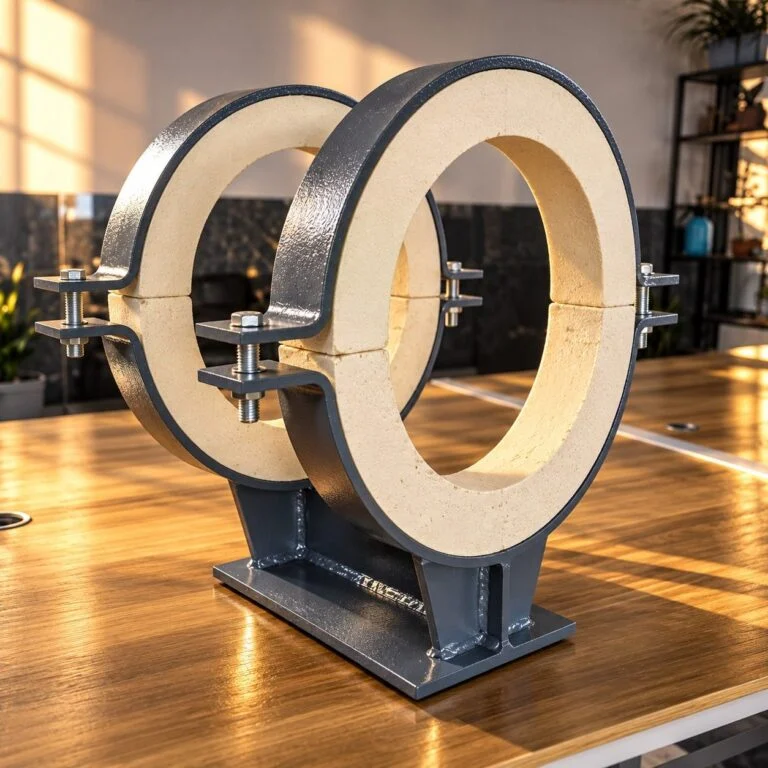
- Nominal pipe size
- 4 in
- Support height H
- 101.6 mm
- Support length L
- 304.8 mm
- Axial movement allowance
- 101.6 mm
Insulated Pipe Support
View details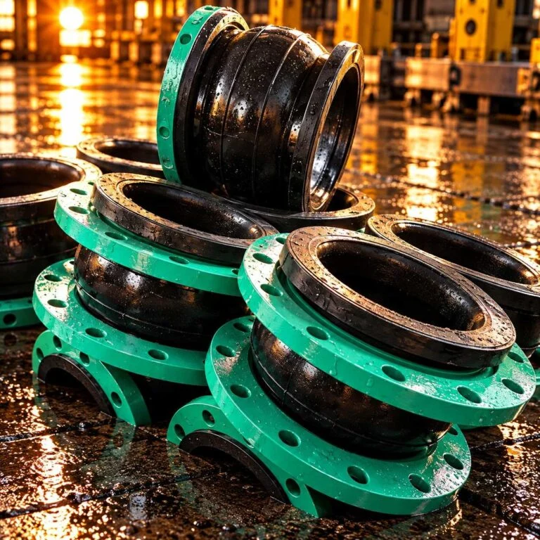
- Nominal size
- DN100 / 4 in
- Face-to-face length
- 150 mm
- Axial extension
- 10 mm
- Axial compression
- 19 mm
Rubber Expansion Joint
View detailsRequest a waterproof casings quotation
For waterproof casings, send actual pipe OD, material, sleeve bore, wall thickness, required length and the wall-penetration drawing. Include water head, pressure direction, expected movement, waterstop and membrane details, coating, seal requirements and quantities.
Attach the approved drawing, item schedule and service conditions. Identify mandatory documents, inspection hold points and delivery requirements when requesting a quotation.
- Drawing-based review
- Service-specific selection
- Inspection scope agreed