
Flexible joints manufacturing for specified movement, sealing and connection geometry. Send JINYI your medium, pressure, temperature and installation dimensions.
Connectors & Flexible Joints Manufacturing
Connectors & Flexible Joints
Manufacturing scope
Stage 01
Define pressure, temperature, face-to-face length and movement in each direction.
Flexible Joints Manufacturing for the installed duty
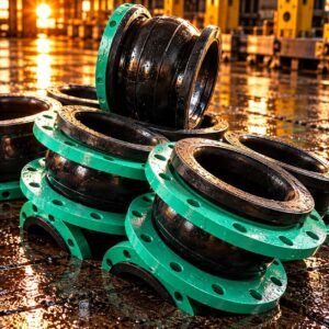
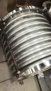
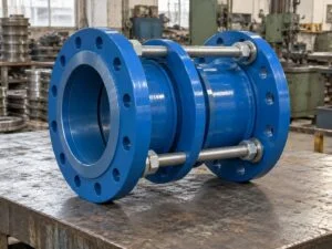
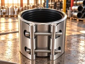
A flexible connector, rubber expansion joint and metal bellows are different components. Specify the intended function before choosing a construction or requesting a quotation.
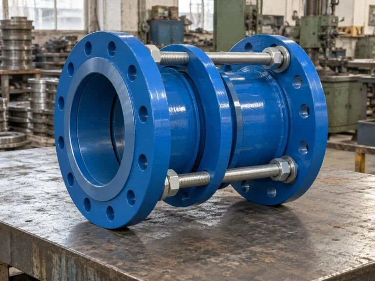
JINYI handles enquiries for connectors, couplings, rubber joints and metal compensators. Flexible joints manufacturing starts with the movement envelope and the connection, including actual pipe outside diameter, flange drilling and installed length. This page covers manufacture and acceptance; browse pipe connectors and couplings or rubber joints and metal compensators for product types. Material, dimensions, testing and production arrangements are confirmed for the order.
Define the connection and its function
Mechanical couplings
Pipe connector manufacturing must account for actual pipe OD, ovality, insertion depth, end gap and gasket compression. A nominal DN designation is not an OD tolerance.
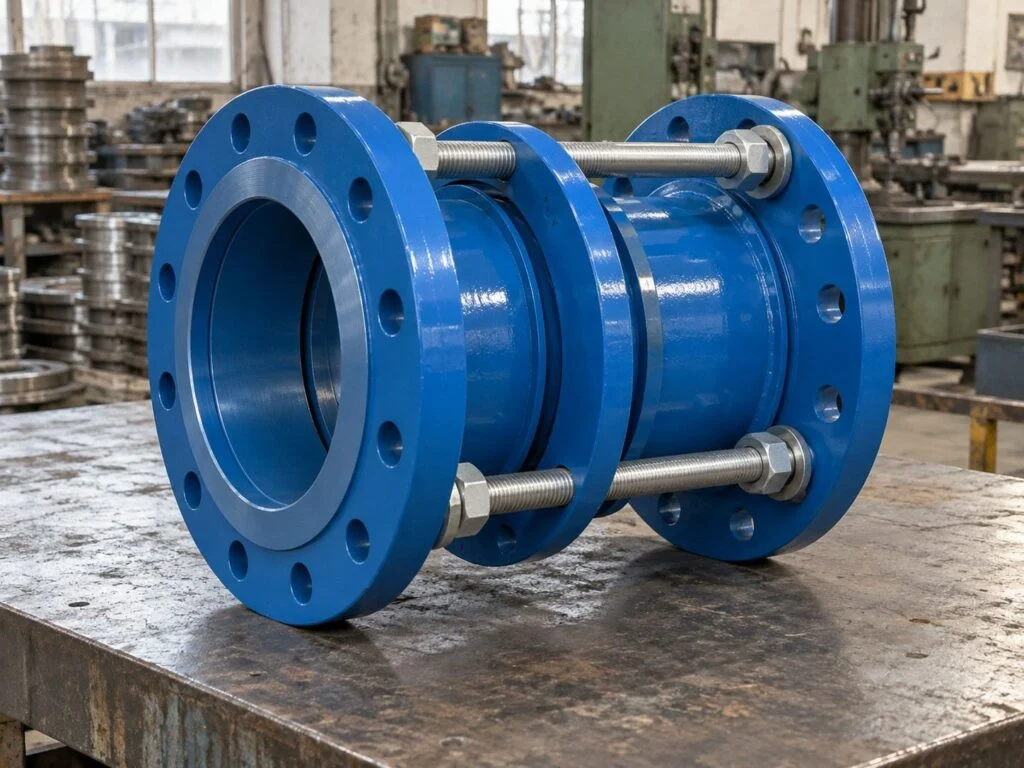
Dismantling joints
Specify installed length, adjustment range, flange drilling and tie-rod arrangement. An installation adjustment allowance does not automatically permit repeated thermal movement.
Rubber expansion joints
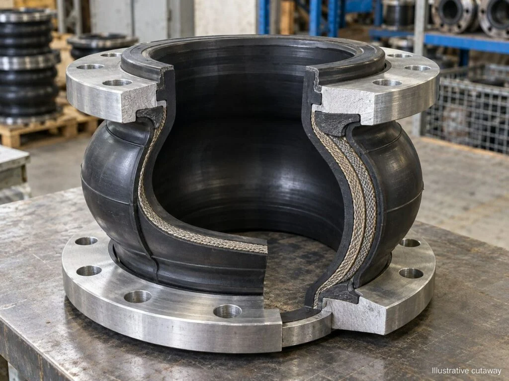
Choose tube compound, reinforcement and cover for the medium, pressure, temperature and environment. Confirm whether vacuum service requires additional support.
Metal bellows assemblies
Define axial, lateral and angular movement, cycle duty and end connections. Bellows geometry, alloy and restraint arrangement require a coordinated design review.
Pressure thrust
Identify anchors, guides and restraints in the piping design. Joint flexibility does not remove the pressure forces acting on the system.
Connection compatibility
Match flange standard, class or PN, facing, gasket and bolt clearance. Equal nominal sizes from different standards may have different drilling.
Assembly records
Request the approved assembly drawing, material identification, inspection scope and test reports. State required witness points before the production schedule is agreed.
Protection for transport
Keep rubber away from incompatible oils and protect bellows from impact. Agree shipping restraints, lifting points and storage instructions for the selected design.
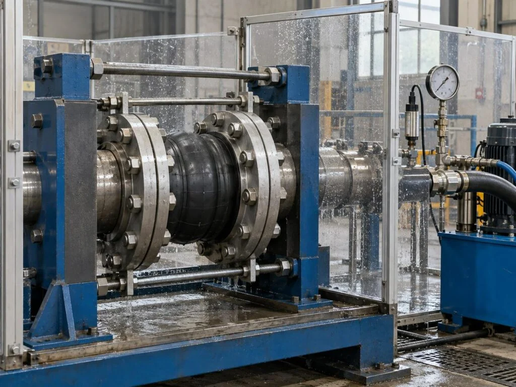
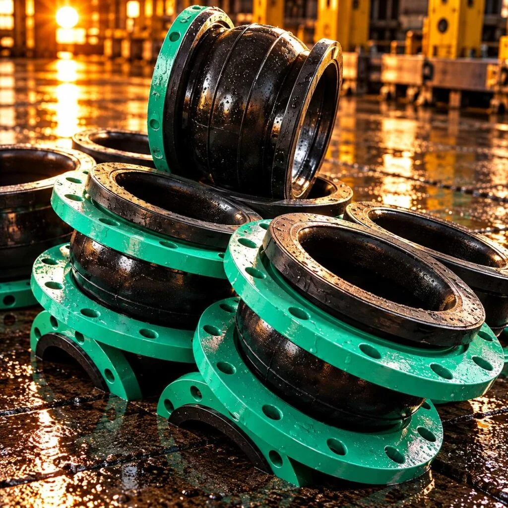
Media includes product views and representative process illustrations. Illustrated equipment and inspection arrangements do not establish an offered capability; the quotation defines the agreed manufacturing and inspection scope.
Connection & Movement
Process Controls
The rubber expansion joint manufacturing process and metallic bellows fabrication need separate controls. Rubber construction requires compound identification, reinforcement placement and a validated curing route. Metallic assemblies require controlled forming and weld quality. Couplings add gasket seating and OD engagement checks. For all three, the assembly drawing must identify the installed geometry and service envelope; a successful static leak test alone does not prove movement capability or fatigue life.
- GeometryActual pipe OD, flange drilling and installed length
- ServiceMedium, pressure, vacuum and temperature
- MovementCompression, extension, offset and cycle duty
controls JINYI Engineering
Duty sheet
Record normal, maximum and upset conditions separately. Include cleaning fluids and outdoor exposure.
Compound choice
Specify the elastomer formulation and compatibility evidence; EPDM or NBR alone is not a complete grade.
Reinforcement
Define carcass construction and bead support for the selected rubber joint pressure rating.
Bellows geometry
Review convolution profile, ply construction, end welds and required movement life.
Pipe engagement
Confirm OD range, insertion marks, end gap and restraint type for the actual pipe material.
Face-to-face length
Use the approved installation dimension. Do not stretch a joint to correct an unapproved pipework error.
Restraint design
Distinguish tie rods, limit rods and control units; their functions depend on the complete assembly.
Sealing surfaces
Check rubber sealing lands, gasket grooves and flange faces for damage or contamination.
Inspection plan
State test method, pressure, duration, sampling and acceptance criteria before production.
Identification
Link the joint marking to its assembly drawing, material records and ordered documentation.
Flexible Joints: Manufacturing Details
Ten controls behind the finished connection
Pipe connector manufacturing combines metal preparation, seal selection and controlled assembly. The stages below identify the technical questions to resolve for your component; they are process requirements, not an inventory of unverified factory machinery.
Flanged pipe assemblies and reducers: product footage. Open video
Flexible Joints Manufacturing: 6 controlled stages
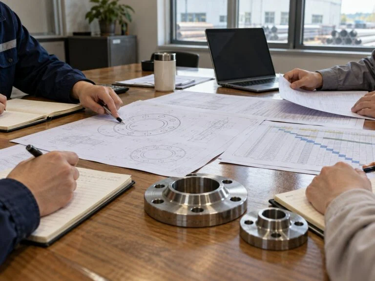
Use this sequence to define the enquiry and acceptance plan. Custom pipe coupling manufacturing services require interface dimensions and pipe details; expansion joints also need a movement specification. The selected route must follow the approved component design and the applicable project requirements.
Review duty and movement
State fluid composition, operating and design temperature, pressure and any vacuum condition. Give axial compression and extension in millimetres, lateral offset in millimetres and angular movement in degrees. Identify simultaneous movements and the number of operating cycles. Add installed length, flange standard and the piping restraint arrangement.
Select metal and elastomer
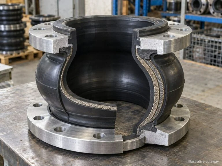
Specify wetted and non-wetted materials separately. Evaluate rubber compatibility with the process fluid and cleaning chemicals; select bellows alloy and end fittings for the corrosion and temperature environment. Agree the material records, compound identification and any potable-water or other approval explicitly required for the application.
Form the joint components
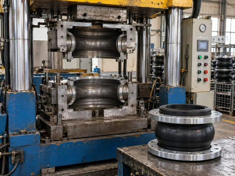
For rubber joints, the route can include mandrel preparation, reinforcement lay-up, moulding and controlled vulcanization. Metal bellows need a qualified forming and welding route appropriate to the design. Coupling bodies and followers require controlled geometry at the seal seats. These are different manufacturing routes, not interchangeable operations.
Machine and assemble interfaces
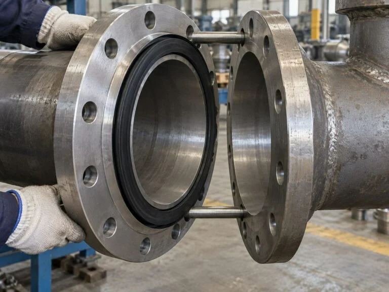
Check flange drilling, face-to-face length, bore clearance and the seating of gaskets or rubber sealing faces. Assemble rods, hinges, followers or other restraints to the approved drawing. Check tool access and fastener engagement. For mechanical couplings, verify the actual pipe OD range and specified end gap before release.
Inspect and test to the plan
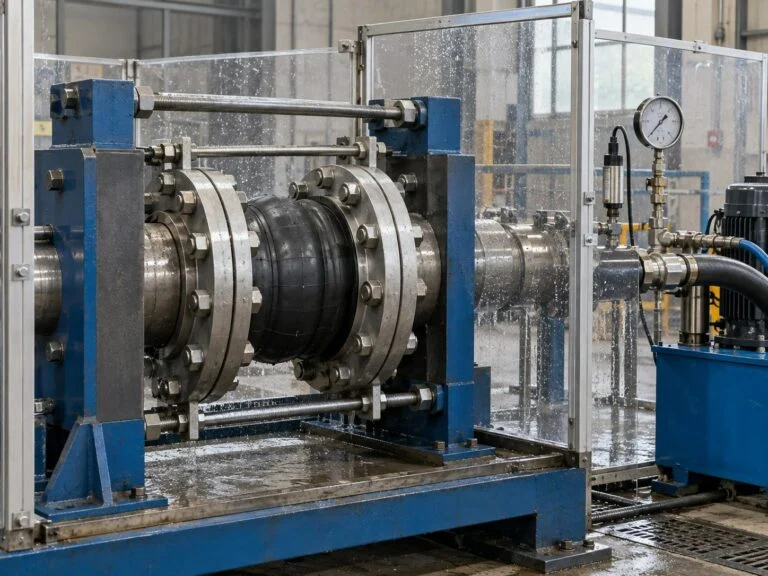
Review visual condition, critical dimensions and identification. Define any pressure or leakage test with its medium, pressure, duration and acceptance criteria. Where movement qualification, weld NDE or material verification is needed, list it separately. A pressure test does not establish the joint fatigue rating or authorize an unsupported installation.
Protect and document shipment
Protect bellows, rubber bodies and sealing surfaces. Identify lifting restrictions and shipping bars where relevant. Supply the ordered reports and assembly information, and match packing labels to the order line. Record recommended storage conditions and the installation dimensions needed by the site team.
Related products
Connectors & flexible joints
Explore flexible joints and mechanical connectors, with the connection and construction details for each family.
View joints & compensators Connectors & couplingsRubber Expansion Joint
A rubber expansion joint connects specified pipe flanges through a flexible elastomer body.
- Flexible elastomer body
- Flanged end connections
Metal Bellows Expansion Joint
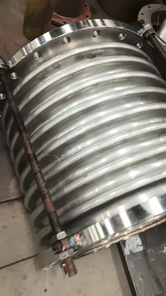
A metal bellows expansion joint uses a corrugated metallic element and end connections to accommodate specified piping movement.
- Corrugated metal bellows
- Flanged assembly
Grooved Pipe Coupling
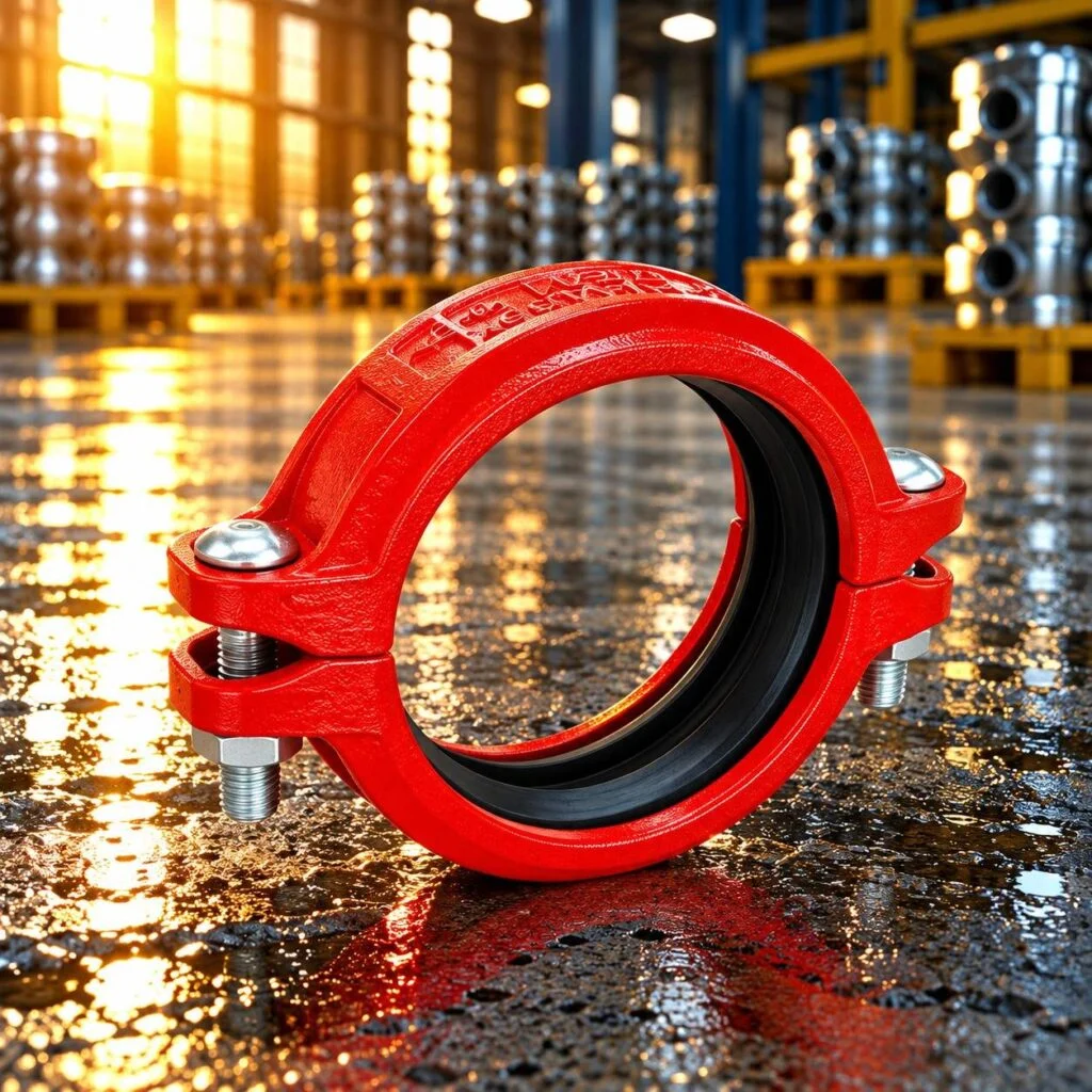
A grooved pipe coupling joins two compatible grooved pipe ends using a gasket and bolted housing.
- Grooved pipe ends
- Gasket and bolted housing
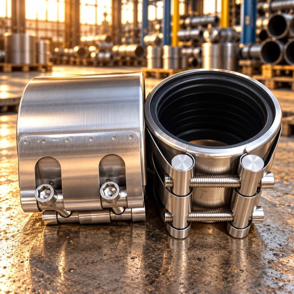
Pipe Repair Coupling
A pipe repair coupling encloses a specified pipe area with a bolted shell and sealing liner.
- Bolted repair shell
- Sealing liner
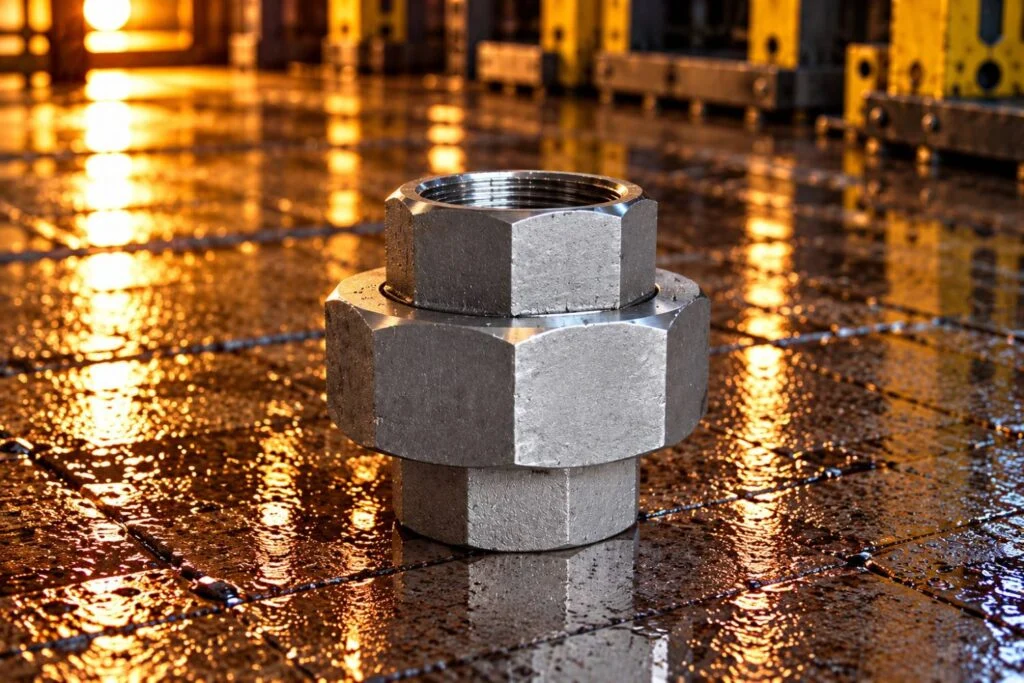
Threaded Pipe Union
A threaded pipe union provides a separable connection between two specified threaded pipe ends.
- Separable threaded joint
- Union-nut connection
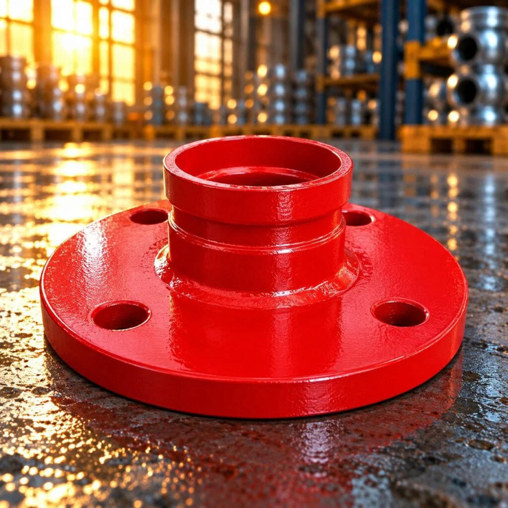
Grooved Flange Adapter
A grooved flange adapter connects a specified grooved piping end to a bolted flange interface.
- Grooved pipe interface
- Bolted flange connection
Materials matched to the medium. Construction matched to movement.
Material names are a starting point, not a universal service approval. EPDM, NBR, stainless steel and carbon steel cover many formulations or grades. Select the actual compound or alloy against fluid chemistry, concentration, temperature, pressure and expected exposure. Confirm the available combination in the quotation.
Specify materials, process and documents for the actual order. Availability is confirmed with quotation.
Specification inputs
Joint manufacturing specification guide
Specify the complete assembly| Property | What to specify | Reference |
|---|---|---|
| Pipe interface | Actual OD and tolerance in mm; pipe material, coating and ovality | Coupling drawing |
| Flange connection | Standard, size, drilling, facing and pressure designation | Mating flange specification |
| Installed length | Face-to-face dimension and installation tolerance in mm | Approved assembly drawing |
| Movement | Axial ±mm, lateral mm, angular degrees and simultaneous duty | Movement schedule |
| Elastomer | Tube and cover compounds, medium, concentration and temperature | Compatibility review |
| Metal bellows | Alloy, end connections, restraint type and required cycle duty | Bellows design review |
| Inspection | Dimensions, traceability, test procedure and report requirements | Order-specific ITP |
Technical references: EJMA bellows guidance, Fluid Sealing Association handbook. EJMA distinguishes axial, lateral and angular movement and warns against torsion. Rubber joint construction and selection have their own guidance. Apply the selected product limits and approved piping design.
Numerical specification examples below explain how to define an enquiry. They are illustrative drawing inputs, not JINYI size, pressure, tolerance or surface-finish guarantees.
| Input | Numerical example | How to specify it |
|---|---|---|
| Installed length | 200 ±2 mm | Illustrative permitted installation length: 198–202 mm. This is an enquiry example, not a rated length for any pictured joint. |
| Movement schedule | −10 / +5 mm | An example axial requirement could be 10 mm compression and 5 mm extension. State lateral offset and angular movement separately; simultaneous capacity requires design review. |
| Unit conversion | 1 MPa = 10 bar | Pressure units must be explicit. Design, operating, vacuum and test conditions are separate entries; no universal test multiplier is assumed. |
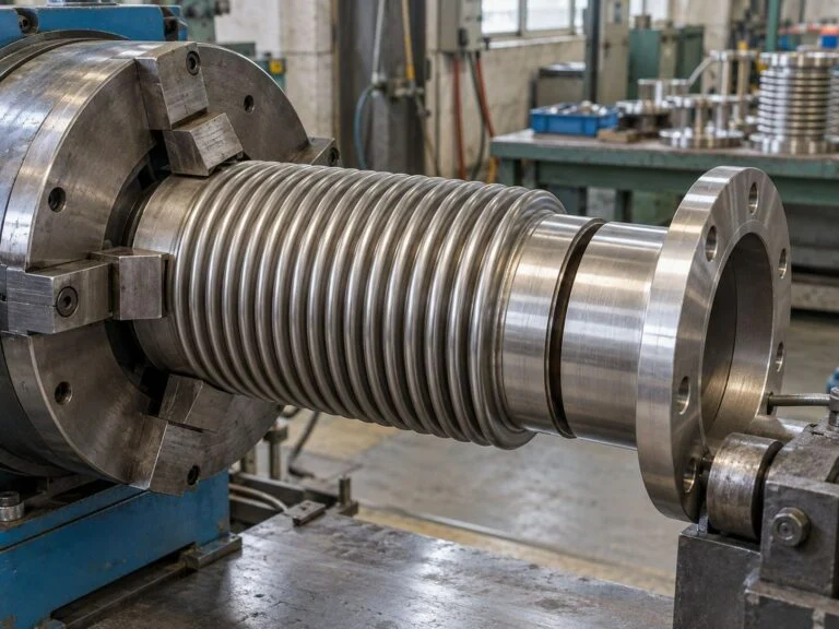
Gauging
Methods
Installed geometry, seal condition and restraint details against the assembly drawing.
- Pipe OD and engagement
- Installed length
- Seal and flange condition
- Restraint configuration
- Identification and records
Define the inspection plan
Documents
Material records, inspection reports and packing list
Measuring equipment
Agree measuring methods, test scope and acceptance criteria for the component.
Drawing-based manufacture
Custom Pipe Coupling Manufacturing Services
Provide the actual pipe OD, pipe material, joint function, flange details and installed envelope. State whether the connection must resist axial pull-out, provide assembly adjustment or accommodate repeated movement. These requirements lead to different body, gasket and restraint designs. A dimensional match alone does not establish functional interchangeability.
For drawing-based assemblies, identify critical datums, seal grooves, fastener details and the revision to manufacture. JINYI can review feasibility, material sourcing, inspection scope and quotation terms. See custom manufacturing and OEM for revision control and first-article requirements.
Technical Guide & Buyer QuestionsBefore you order
Practical answers for flexible joints manufacturing. Use these points to prepare a technical enquiry and agree acceptance. These are specification examples and buyer guidance, not customer project or testimonial claims.
Buyer guide What does flexible joints manufacturing include? Construction-specific scope The scope may cover a rubber body, metal bellows, mechanical coupling or dismantling assembly. Define the function first, then agree materials, geometry, manufacturing route and inspection. Supply-only and drawing-based orders can require different engineering and document responsibilities.
Buyer guide Which movement values are needed? Specify directions separately List compression, extension, lateral offset and angular movement with units and operating cycles. State which occur together. Maximum values quoted for separate directions must not automatically be combined in one operating condition. Include installation temperature and preset requirements for engineering review.
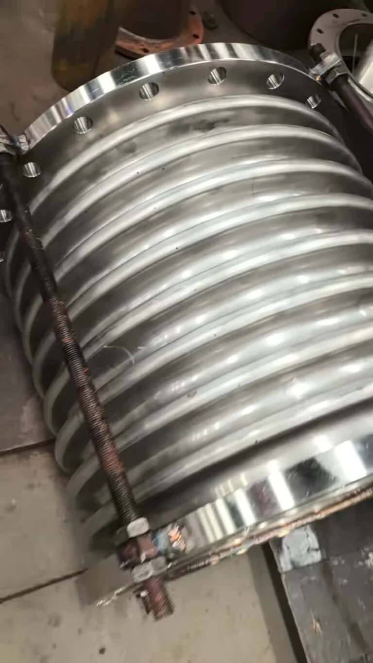 Buyer guide Can a coupling replace an expansion joint? Check intended function
 Not automatically. A coupling may join or restrain pipe ends without allowing repeated thermal movement. A dismantling joint may provide installation adjustment only. Confirm the documented movement capability and pressure restraint of the exact design before treating it as an expansion joint.
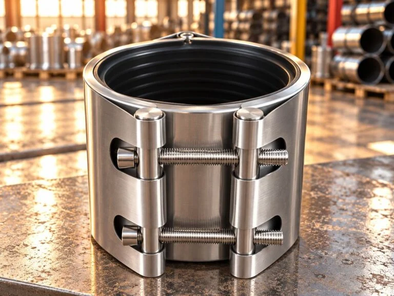 Buyer guide Does a flexible joint remove pressure thrust? Restraints remain part of the system
 Internal pressure creates forces that must be carried by the approved joint restraint and piping support arrangement. Obtain the relevant design loads. Do not assume rubber flexibility, a bellows or an added rod eliminates the need for an engineered anchoring and guiding arrangement.
Buyer guide How is the rubber compound selected? Use the full service chemistry Give the fluid constituents, concentration, continuous temperature, upset temperature and cleaning chemicals. NBR is often considered for oily media and EPDM for suitable water duties, but formulation-specific compatibility and assembly ratings must be confirmed. A generic elastomer name does not prove approval.
Buyer guide What is checked during rubber joint manufacture? Body and assembly controls The rubber expansion joint manufacturing process needs controls for compound identity, reinforcement position, bead construction, curing and visible defects. Final assembly checks address flange interfaces and installed length. Testing and record requirements should be agreed before manufacture.
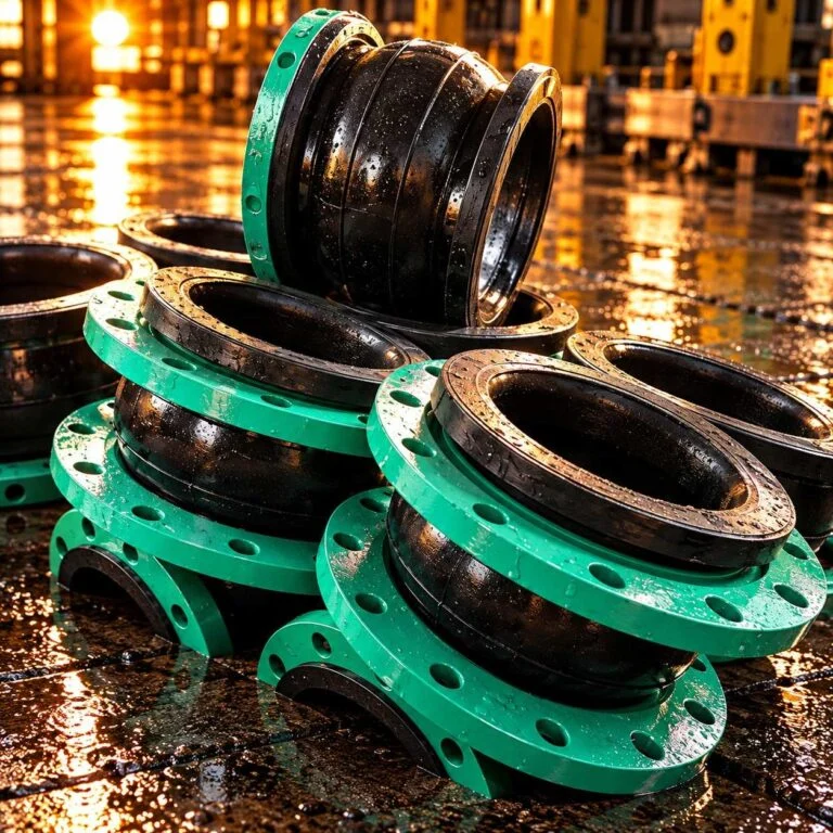 Buyer guide Can a metal bellows take torsion? Avoid twisting the bellows
 Torsion is not a substitute for angular or lateral movement. EJMA warns that twisting can shorten bellows life or cause failure. Identify installation and operating conditions that could apply torque and have the piping arrangement reviewed before procurement.
Buyer guide How should flange drilling be specified? Name the standard and edition Provide the nominal size, class or PN, facing, bolt circle, hole count and mating-flange details. A flange label alone may leave ambiguity. Check fastener access and gasket compatibility, especially where the rubber joint sealing face contacts the mating flange.
Buyer guide Is a leak test enough for acceptance? Separate routine and design checks A documented leak or pressure test evaluates specified conditions on the tested assembly. It does not by itself verify movement fatigue, chemical life or every temperature condition. State dimensional inspection, design qualification and production testing as separate acceptance requirements.
Buyer guide What should a coupling RFQ contain? Custom pipe coupling manufacturing services Send pipe OD and tolerance, material, wall thickness, medium, pressure, temperature, end gap, axial restraint requirement and quantity. Attach the assembly drawing where available. Add coating condition, installation access and document requirements so competing quotations cover the same scope.
Buyer guide What matters for vacuum service? Review the complete joint Provide the minimum absolute pressure or vacuum level, temperature and operating cycle. Confirm whether the selected rubber joint or bellows needs additional design provisions. A positive-pressure rating does not automatically establish suitability for vacuum or external pressure.
Buyer guide How are shipment and installation linked? Protect the approved geometry Specify protection, storage conditions and identification. Request the installation instructions for the exact assembly, including restraint settings and shipping-bar removal where applicable. The receiving team should check for transport damage before the joint enters the pipeline.
Specify the joint around the duty.
Ready to share your joint duty sheet?
Send pressure, temperature, medium, movement, pipe OD, installed length and flange details. JINYI will review the technical scope and confirm the quotation basis.
Get a quote Confirm the drawing, service conditions and inspection scope before production starts.
JINYI Engineering teamStart here
Start Your Flexible Joints Manufacturing Enquiry
Send pressure, temperature, medium, movement, pipe OD, installed length and flange details. JINYI will review the technical scope and confirm the quotation basis.
JINYI Pipe FittingsCangyan Road Industrial Park · Yanshan County · Cangzhou · Hebei