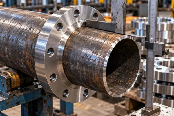
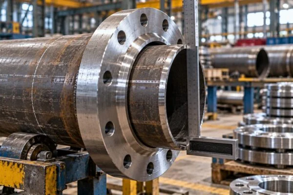
Slip On Flange technical overview.
Slip On Flange from JINYI is specified by its application, material and connection or drawing requirements. Review the selection schedule and enquiry requirements below to prepare a quotation for your project.
On this page
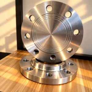
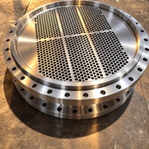
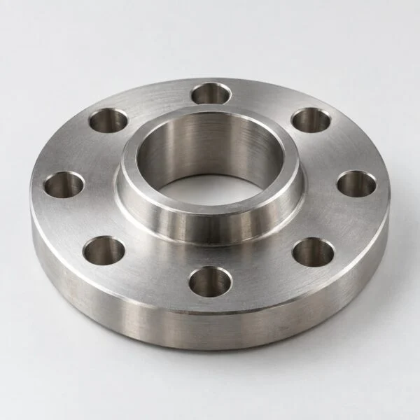
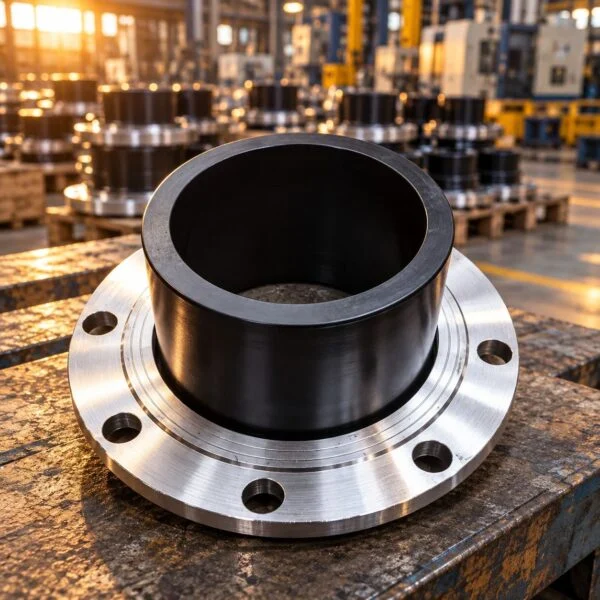
Specification basis: The schedule below distinguishes industry geometry from order-specific requirements. Final dimensions, performance and price are defined in the approved quotation and drawing. Photographs identify the product family.
What is a slip on flange?
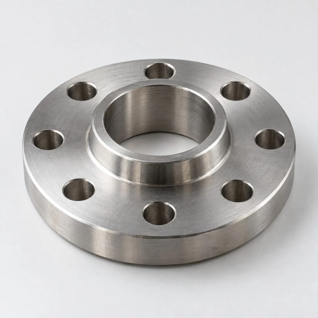
A slip on flange has a bore that fits over the pipe and a hub that locates the welded connection. It provides a detachable bolted interface while using a different pipe attachment arrangement from a weld neck flange.
Key dimensions and installation fit
For the NPS 4 Class 150 reference, the 114.3 mm pipe OD fits a 116.1 mm flange bore. The hub diameter is 134.9 mm and the raised-face diameter is 157.2 mm. Confirm the applicable standard edition, facing and material before ordering; Class 150 is not a universal working pressure in psi or bar. Compare related configurations: threaded flange, blind flange.
How to specify the slip on flange
Start with the pipe outside diameter and bore clearance, then identify the required flange standard, facing, pressure class and material grade. Slip on and plate flanges can look similar; specify the hub profile and welding detail to avoid substituting a different design.
Check the mating flange's outside diameter, drilling, facing and gasket arrangement together. Nominal size describes the pipe family, while the measured diameters define the physical interface. A PN or Class designation has a material-dependent pressure-temperature basis; it is not a universal working pressure in bar.
Technical data for the slip on flange
| Dimensional reference | ASME B16.5, NPS 4, Class 150 RF |
|---|---|
| Pipe outside diameter | 114.3 mm |
| Flange outside diameter | 228.6 mm |
| Bore diameter | 116.1 mm |
| Minimum flange thickness | 23.9 mm |
| Overall hub length | 33.3 mm |
| Hub outside diameter | 134.9 mm |
| Raised-face diameter | 157.2 mm |
| Bolt circle diameter | 190.5 mm |
| Bolt holes | 8 × Ø19.1 mm |
| Material selection | Specify ASTM A105 or the required ASTM A182 grade |
| Pressure-temperature basis | Selected material group and standard edition |
Sizes and dimensional requirements
Use the named standard for standardized interfaces and the controlled drawing for custom dimensions. Confirm units, diameter datums, minimum finished thickness and any mating-component requirements. A catalogue dimension is not a universal tolerance, capacity or pressure rating.
Dimensions and tolerance schedule
| Individually toleranced features | Limits and datum system on the approved drawing |
|---|---|
| Standardized flange dimensions | Applicable flange standard and edition; thread standard separately |
| Functional acceptance | Agreed inspection method and acceptance criteria |
Individually toleranced dimensions and functional requirements take precedence over a general tolerance note. Specify the governing standard and acceptance method in the order documents; a tolerance shown by another manufacturer does not establish JINYI manufacturing capability.

Materials, inspection and documentation
Measure the bore or thread, overall height, flange thickness, bolt circle and hole pattern. Inspect the gasket seating face for damage and specify its finish. Verify the material designation and marking against the order. Include the gasket and bolting specification when defining the complete assembled joint.
State the exact material designation and supplied condition, the controlled drawing revision and the required inspection reports before ordering. Separate material certification from dimensional checks and functional or pressure testing. Agree the acceptance limits for the ordered component and identify any additional witnessing, marking or packing requirements. For production steps and inspection considerations, see flanges and fittings manufacturing.
Installation and handling guidance
The welding procedure defines the inside and outside attachment welds. Position the flange face square to the pipe and keep the gasket seating area free of weld spatter. Check pipe insertion depth and bolt access against the installation drawing.
Where the slip on flange is used
- Process pipework. Detachable connections between piping, valves and equipment.
- Equipment nozzles. Drawing-matched interfaces for the connection standard and facing.
- Maintenance. Replacement components selected by dimensions and material, with access for assembly.
How to order a slip on flange
Send the required configuration, material, quantity, destination and controlled drawing to JINYI. Identify changed dimensions, mating components, operating conditions and inspection scope. For a repeat order, include the previous approved revision and state any changes. The final quotation defines the supplied geometry, documentation, price and delivery terms.
Quantity prices and order preparation
| 1–49 pcs | US$9.80 / piece |
|---|---|
| 50–99 pcs | US$9.40 / piece |
| 100+ pcs | US$9.00 / piece |
Indicative budget pricing selected from public supplier listings. Published comparison: US$9.80 / 9.40 / 9.00 at 1–49 / 50–99 / 100+ pieces. CZIT slip-on flange listing. Final JINYI pricing depends on the confirmed specification, quantity, inspection and delivery scope. Quantity-specific terms are confirmed with the final quotation.
Engineering and pricing references
Haihao Class 150 slip-on flange dimensional table; ASME B16.5 scope. These sources explain the named product geometry or selection method. Their certifications, rated capacities and manufacturing capabilities belong to the named organizations.
Other JINYI products worth comparing
Review the industrial pipe flanges catalog for adjoining components, connection choices and alternative product forms.
Request a slip on flange quotation from JINYI with the drawing, material and quantity required for your project.
Slip On Flange selection and quotation checklist
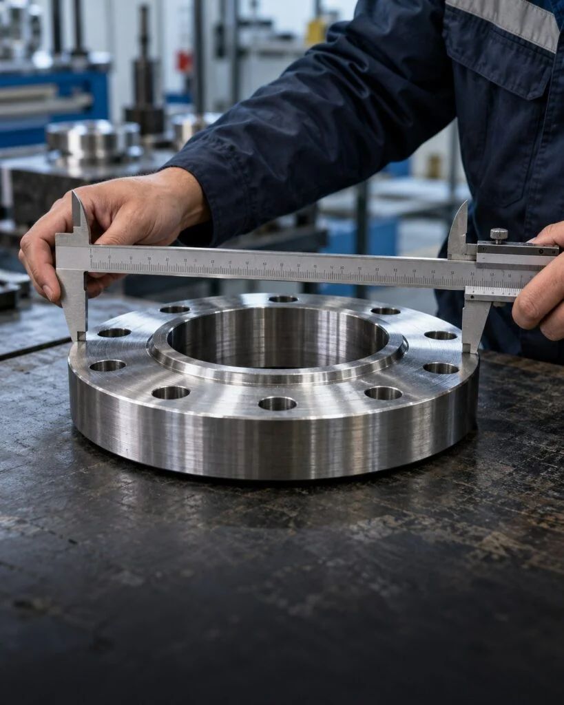
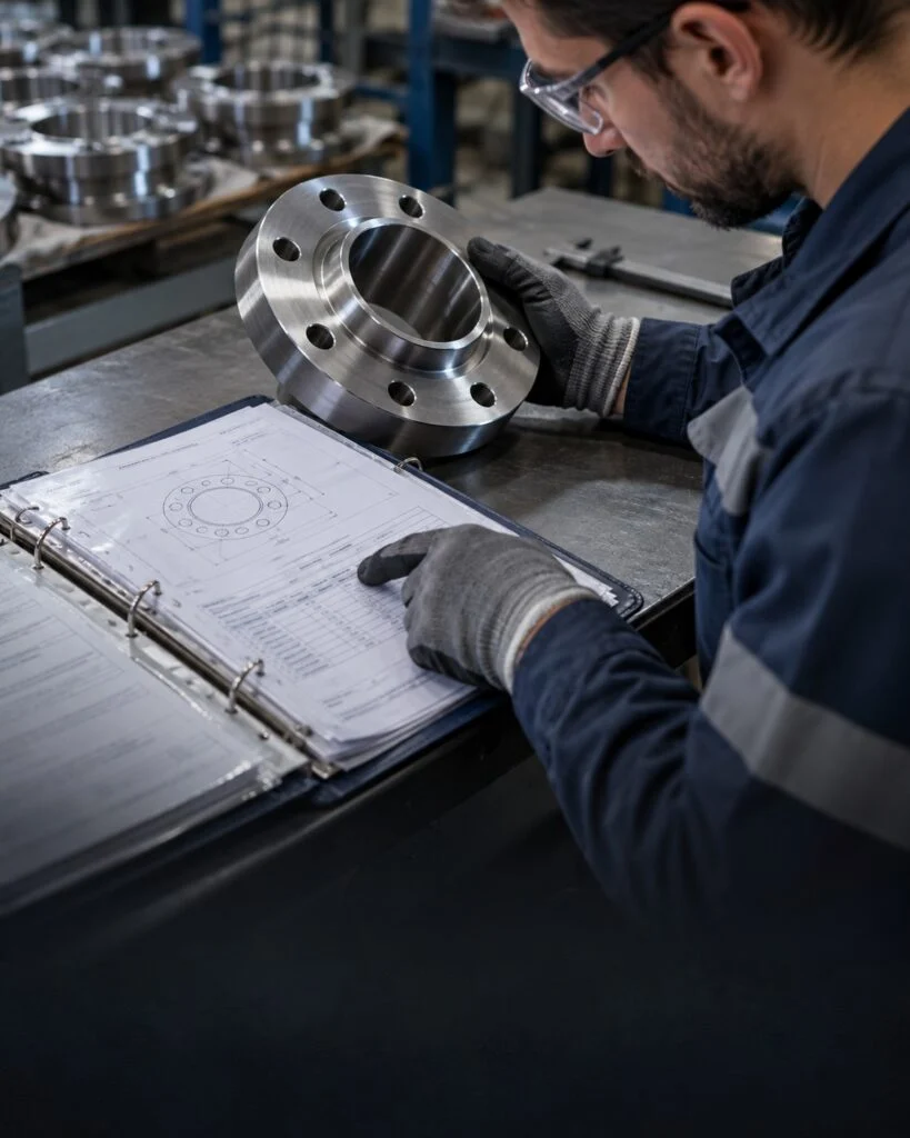
The flange slips over the pipe and uses its specified attachment weld detail. Identify insertion position, inside and outside welds and hub dimensions when comparing a plate flange. Use the photographed product form to identify the arrangement, then use the controlled drawing to define what will be supplied. Similar-looking components can have different end details, load paths or maintenance requirements.
Slip On Flange dimensions and tolerances
The first comparison for this slip on flange is bore clearance and hub height. Mark the dimensions that control mating, alignment and installation space on the enquiry drawing. Give units for every value and identify the datum from which it is measured. If a dimension is critical, specify its individual tolerance and measurement method rather than relying on a general tolerance note.
For the NPS 4 Class 150 reference, the 114.3 mm pipe OD fits a 116.1 mm flange bore. The hub diameter is 134.9 mm and the raised-face diameter is 157.2 mm. Confirm the applicable standard edition, facing and material before ordering; Class 150 is not a universal working pressure in psi or bar. Review the selection schedule together with the final drawing and inspection requirements.
Prepare the material and interface information
For a slip on flange enquiry, identify the required material designation and supplied condition. Describe the mating components, attachment method and environment. Include the operating temperature and any relevant pressure, movement or structural load. These inputs should describe the actual installation, including changes between normal operation, start-up and maintenance where applicable.
Specify coatings, surface finish and marking separately from the base material. If traceability is needed, identify the record required and how it must correspond to the delivered component. Agree whether inspection covers dimensions, material documentation, welds or functional testing; these are different checks with different acceptance criteria.
Custom slip on flange quotation
Attach the latest drawing revision, required quantity and delivery destination when contacting JINYI. Highlight departures from the illustrated arrangement, including changed dimensions, connections, finish and packing. For repeat orders, reference the approved configuration and list changes explicitly so an earlier drawing is not assumed to remain current.
Compare quotations using the same geometry, grade, supplied condition, unit of supply and inspection scope. A piece, a segment and a complete assembly can represent different quantities. Confirm quantity discounts and delivery terms with the final quotation.
Compare related component arrangements
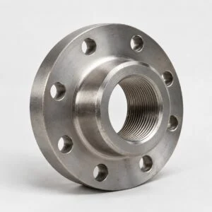
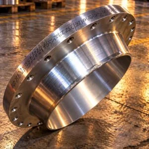
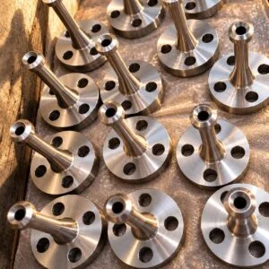
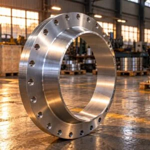
Evaluate this slip flange by its actual bore clearance and hub height and the required pipe flange arrangement. The photographs below show separate JINYI products for comparison. They are linked to their own technical pages and are not additional gallery views of this slip on flange.
| Photo | Related product | Selection detail |
|---|---|---|
 | Plate Flange | Bore clearance and bolt drilling. Compare this separate product when the drawing requires its particular arrangement. |
 | Weld Neck Flange | Hub geometry and pipe bore. Compare this separate product when the drawing requires its particular arrangement. |
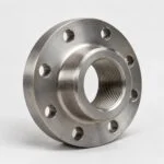 | Threaded Flange | Thread standard and bolt pattern. Compare this separate product when the drawing requires its particular arrangement. |
Questions to resolve before ordering
Which dimensions need checking first?
Start with bore clearance and hub height and the mating or mounting detail. Check nominal designations against measured dimensions, then review the installation envelope. Photographs help identify the form; the drawing provides the dimensional basis for acceptance.
What should the quotation include?
A slip on flange quotation should identify the configuration, drawing revision, material, quantity, price basis and agreed inspection records. Keep these details together with the approved order so receiving inspection can compare the delivered product with the specified component.
Independent terminology reference
ASME flange standard scope provides an independent reference for component terminology. Use the specified standard and edition where required by the project. This link does not establish JINYI certification, product approval or interchangeability with another manufacturer.
- Spec
- Defined configuration
- Grade
- Material requirement
- US$9.80
- Indicative unit price
- 3
- Quantity bands
- Product arrangement — ASME B16.5 · NPS 4 · Class 150 RF
- Engineering selection — For the NPS 4 Class 150 reference, the 114.3 mm pipe OD fits a 116.1 mm flange bore. The hub diameter is 134.9 mm and the raised-face diameter is 157.2 mm. Confirm the applicable standard edition, facing and material before ordering; Class 150 is not a universal working pressure in psi or bar.
- Quotation scope — Material, drawing revision, quantity, inspection and delivery terms confirmed together
At a glance
- Product form
- ASME B16.5 · NPS 4 · Class 150 RF
- Dimensional reference
- ASME B16.5, NPS 4, Class 150 RF
- Pipe outside diameter
- 114.3 mm
- Flange outside diameter
- 228.6 mm
- Pricing
- Indicative USD pricing
| Dimensional reference | ASME B16.5, NPS 4, Class 150 RF |
|---|---|
| Pipe outside diameter | 114.3 mm |
| Flange outside diameter | 228.6 mm |
| Bore diameter | 116.1 mm |
| Minimum flange thickness | 23.9 mm |
| Overall hub length | 33.3 mm |
| Hub outside diameter | 134.9 mm |
| Raised-face diameter | 157.2 mm |
| Bolt circle diameter | 190.5 mm |
| Bolt holes | 8 × Ø19.1 mm |
| Material selection | Specify ASTM A105 or the required ASTM A182 grade |
| Pressure-temperature basis | Selected material group and standard edition |
| Individually toleranced features | Limits and datum system on the approved drawing |
|---|---|
| Standardized flange dimensions | Applicable flange standard and edition; thread standard separately |
| Functional acceptance | Agreed inspection method and acceptance criteria |