
Pipe supports manufacturing and wall sleeve fabrication for defined loads, pipe movement and penetration geometry. Send JINYI your support schedule and drawings.
Pipe Supports & Casings Manufacturing
Supports, Casings & Wall Sleeves
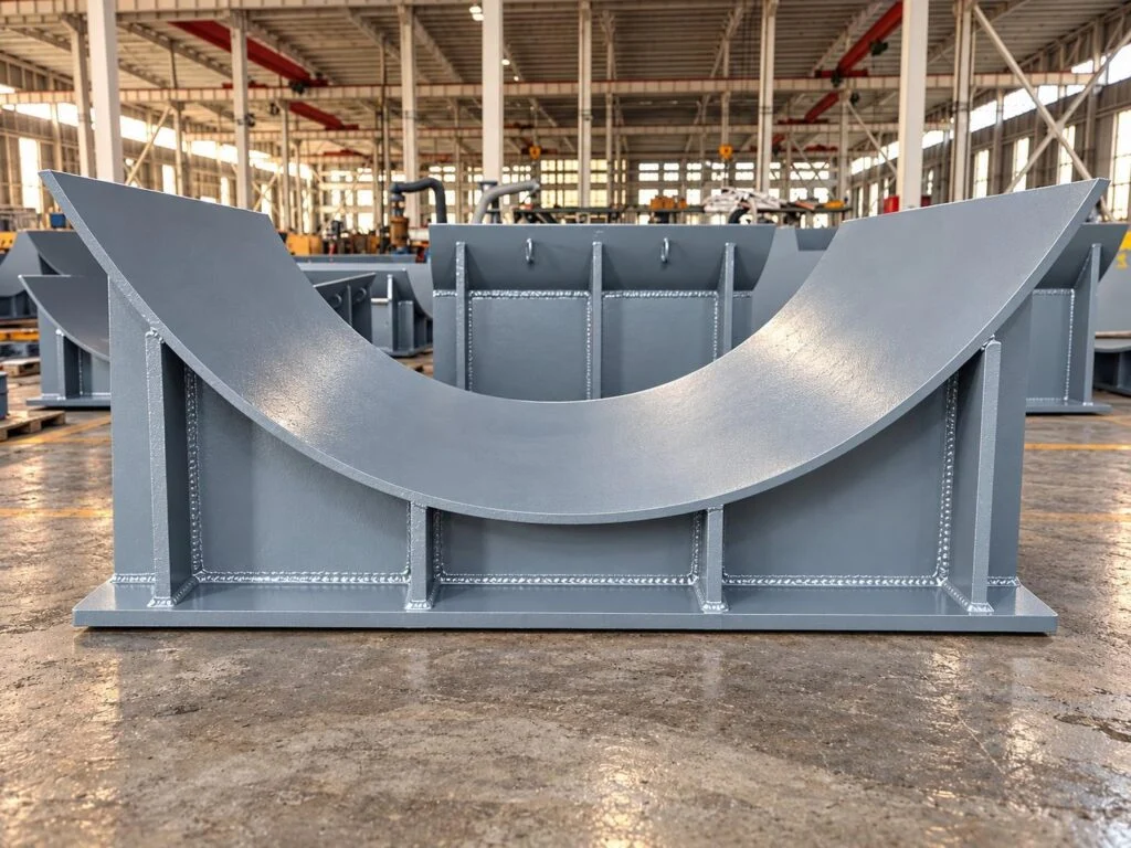
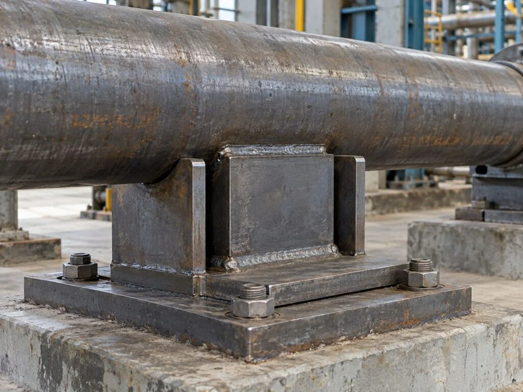
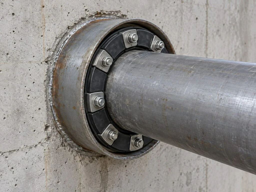
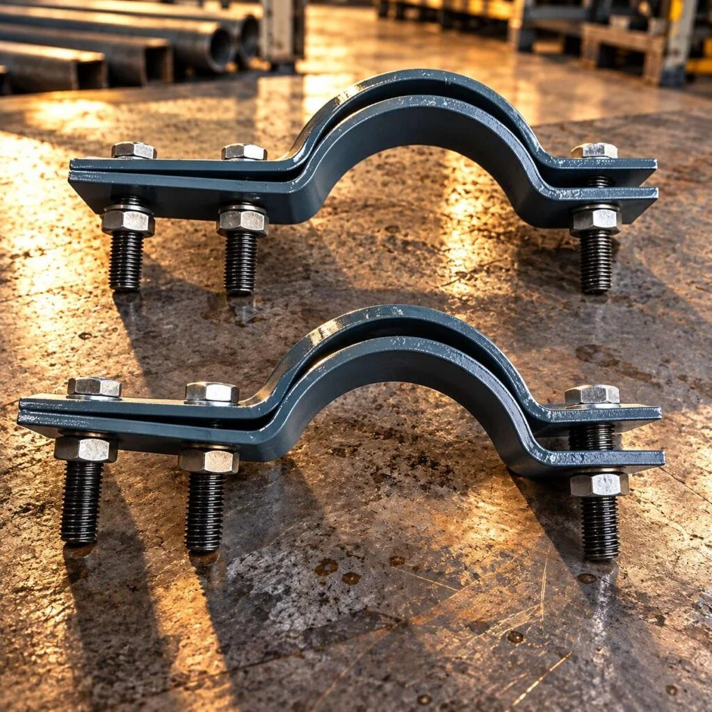
Manufacturing scope
Stage 01
Identify vertical and lateral loads, pipe movement and the support or sleeve drawing.
Pipe Supports Manufacturing from loads to interfaces
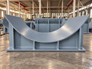
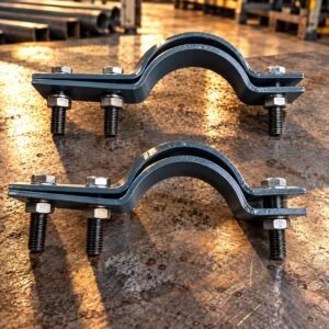
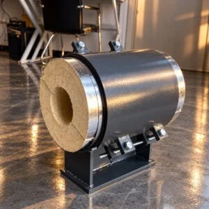
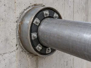
A support carries or restrains loads. A wall sleeve forms a penetration interface. Specify these functions separately, even when both components appear on the same installation drawing. Compare the spring pipe hanger for a suspended support arrangement and the rigid wall sleeve for a pipe passage through a wall.
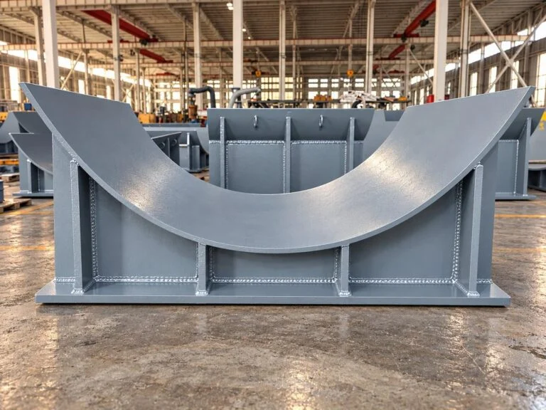
JINYI receives enquiries for pipe supports, hangers, casings and sleeves used in industrial and building services. Custom steel pipe support fabrication starts from the support function, loads and movement; wall sleeve fabrication starts from pipe OD, opening geometry and the sealing detail. Browse pipe supports and hangers or waterproof casings and sleeves for product configurations. The order drawing, material and acceptance plan define the manufacturing scope.
Separate load paths from sealing details
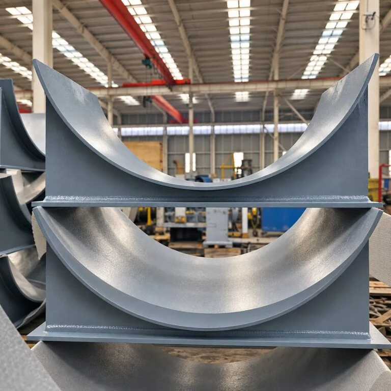
Pipe shoes and saddles
Define contact geometry, shoe height, attachment and bearing length. Include pipe wall, insulation and operating movement when checking the load path.
Clamps and hangers
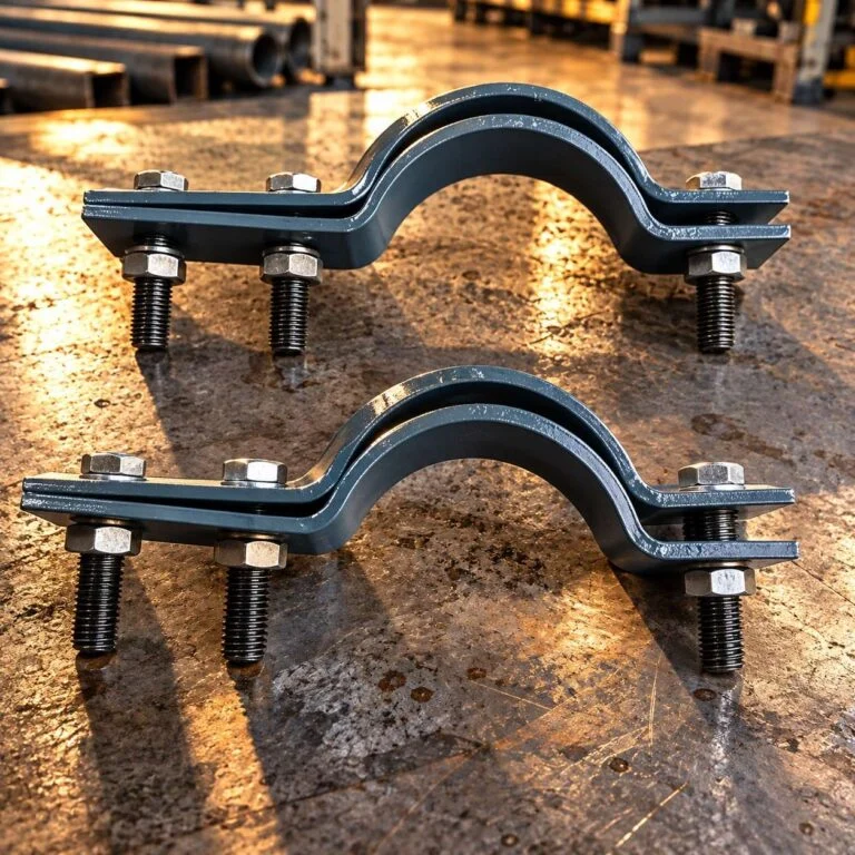
Specify pipe OD, liner thickness, rod size and connection details. Installation clearance and adjustment range must be part of the drawing.
Guides and restraints
Identify which direction is restrained and which remains free. Guide gaps and sliding surfaces affect how the pipe moves under temperature changes.
Wall casings and sleeves
State sleeve ID, wall thickness, length, puddle-flange location and sealing arrangement. Coordinate the penetration with the finished wall and pipe alignment.
Defined design loads
Provide operating, empty and hydrotest cases as applicable. State load directions and units; a pipe diameter alone does not establish support capacity.
Controlled weld details
Specify joint preparation, weld sizes and acceptance requirements. Determine whether qualified procedures, personnel and NDE are required by the project.
Compatible protection
Choose galvanizing, paint or stainless construction for exposure and service. Coatings can affect thread fit, sliding surfaces and seal clearances.
Installation identification
Use support tags and drawing revisions to match assemblies to the layout. Mark orientation where a reversed guide or sleeve would affect installation.
Media includes product views and representative process illustrations. Illustrated equipment and inspection arrangements do not establish an offered capability; the quotation defines the agreed manufacturing and inspection scope.
Fabrication & Penetration
Process Controls
Pipe supports manufacturing must preserve the load path from the pipe contact surface through the fabricated assembly to the building or steelwork connection. Check weld access, plate orientation, slots, adjustment and sliding clearance before fabrication. The waterproof pipe casing manufacturing process adds concentricity, wall length and seal-seat requirements. Manufacturing to dimensions does not replace the designer’s verification of structural loads, anchors or the complete wall sealing system.
- LoadsVertical, lateral, uplift and temporary cases
- MovementThermal travel, guide gap and sliding surface
- PenetrationPipe OD, sleeve ID, wall thickness and seal detail
controls JINYI Engineering
Support function
Label each assembly as a rest, hanger, guide, stop or anchor as specified by the designer.
Load schedule
Record load directions, units, combinations and the drawing revision used for fabrication.
Pipe contact
Check saddle radius, clamp ID and liner allowance against actual pipe OD and insulation.
Plate preparation
Control thickness, cut edges, slot geometry and hole locations from defined datums.
Weld geometry
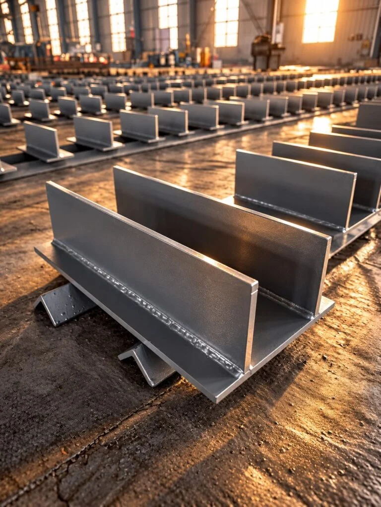
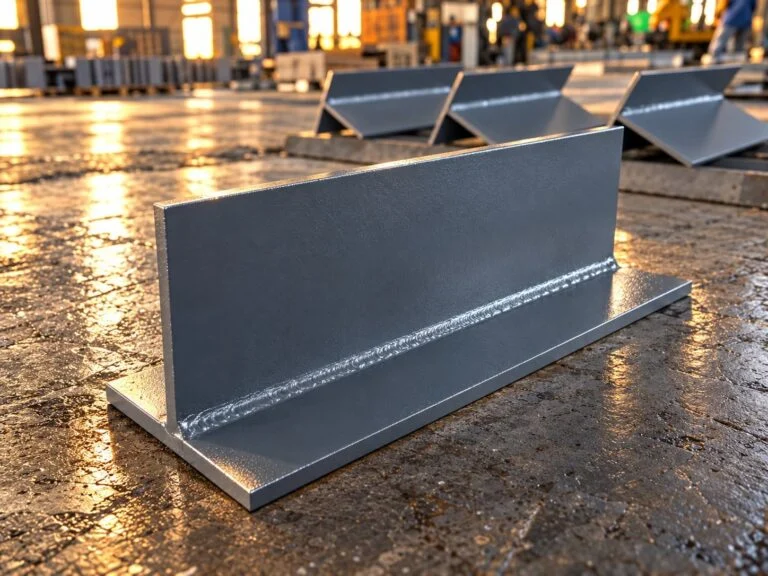
Specify weld type, size, length and access without blocking intended adjustment or drainage.
Thermal clearance
Provide the specified guide gap and travel; coating thickness must be included where relevant.
Sleeve dimensions
Confirm finished ID, length, perpendicularity and the puddle-flange position.
Sealing interface
Coordinate annular space, seal compression and fastener access with the selected seal system.
Protective finish
Define surface preparation, coating system and required thickness or galvanizing specification.
Release checks
Match support tags, dimensions, ordered records and packing to the installation schedule.
Supports & Sleeves: Fabrication Details
Ten checks that improve site fit-up
Custom steel pipe support fabrication and sleeve production share cutting, forming and welding operations, but their acceptance requirements differ. Use these controls to connect the shop drawing to the actual piping layout and wall penetration.
Split pipe clamps and metal fabrication: workshop footage. Open video
Pipe Supports Manufacturing: 6 fabrication stages
Confirm the component function before agreeing the manufacturing route. Pipe supports manufacturing uses a load and movement schedule; wall sleeve fabrication uses a coordinated penetration drawing. The following stages create an order-specific inspection and release plan without assuming one support design or seal detail suits every site.
Review drawings and design inputs
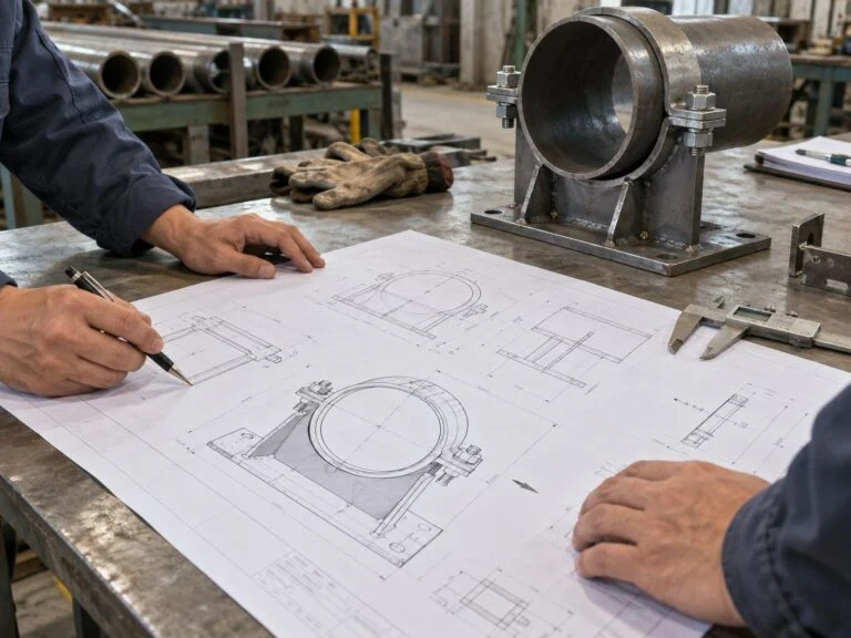
Provide support tags, pipe OD, material, support type and connection details. Include load vectors, operating temperature, thermal travel and temporary cases defined by the designer. For sleeves, provide wall thickness, sleeve ID and length, flange position and the proposed seal. Resolve civil, piping and structural interface conflicts before cutting.
Identify stock and prepare blanks
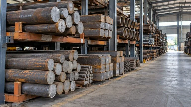
Check the specified plate, section, tube and fastener materials. Record thickness and any required material traceability. Cut blanks to allow for forming and weld preparation, and remove burrs that would interfere with fit-up. Do not treat a similar commercial material designation as an approved substitution.
Form and fit the components
Form clamps, saddles and sleeve sections to the required profile. Establish controlled datums for baseplates and bolt patterns. Check pipe-contact surfaces, liner allowance and the relationship between sleeve bore and puddle flange. Fixture the assembly to maintain alignment while allowing access for the specified welds.
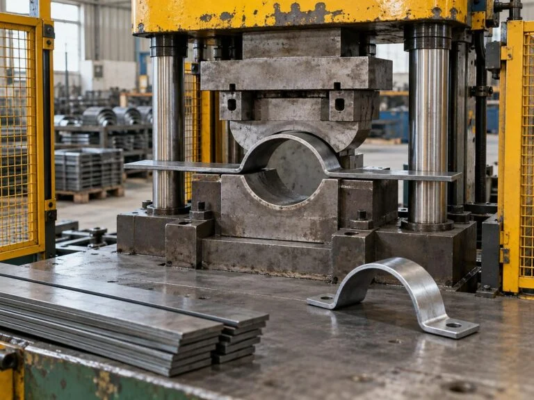
Weld and control distortion
Apply the welding requirements stated in the project specification. Sequence joints to limit baseplate bow, sleeve ovality and misalignment. Check weld size and accessibility, and perform specified examinations before they are obscured by coatings. Where pressure-boundary or code work is involved, confirm the applicable qualification and inspection obligations.
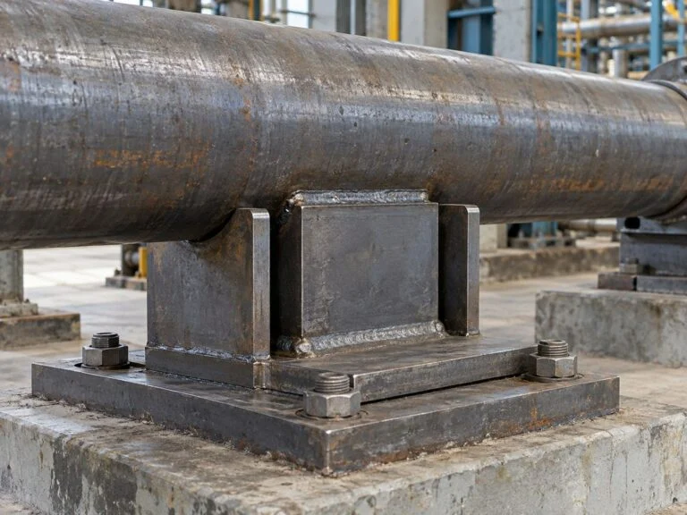
Inspect and apply protection
Verify critical dimensions, guide gaps, travel allowance, sleeve ID and flange location. Agree the scope of weld inspection and coating checks. Apply the specified paint or galvanizing system with allowances for fit. Inspect contact and sealing zones after finishing; excess coating can change a close fit or prevent correct seal installation.
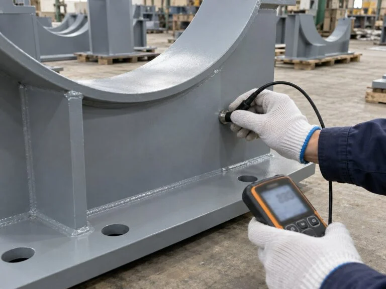
Tag and pack for installation
Identify every assembly with its support or penetration tag and drawing revision where required. Include loose plates, nuts, rods or gasket components listed in the order. Protect finished surfaces and bundle matched parts. Supply the agreed material, dimensional and coating records with a packing list linked to the site schedule.
Related products
Supports & wall sleeves
Explore fabricated supports, insulated assemblies and sleeves for wall penetrations.
View pipe supports Waterproof sleeves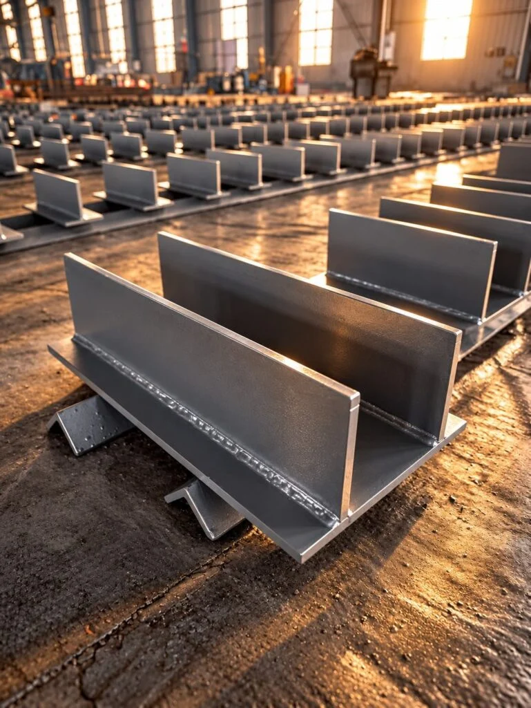
Welded Pipe Shoe
A welded pipe shoe raises the pipe above its supporting steel and transfers the pipe reaction through a fabricated section.
- Welded pipe attachment
- Fabricated support section
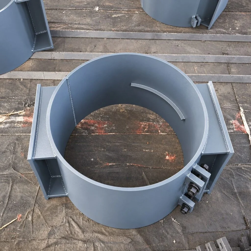
Riser Pipe Clamp
A riser pipe clamp is a bolted attachment for a vertical pipe run.
- Vertical pipe support
- Bolted clamp attachment
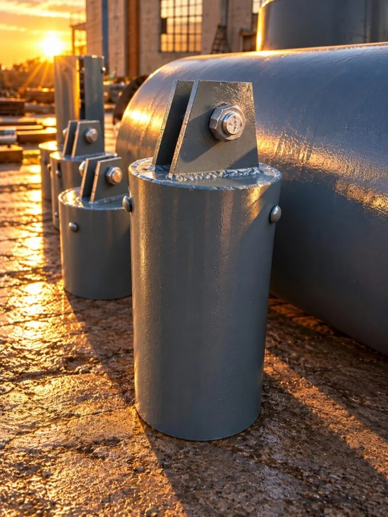
Spring Pipe Hanger
A spring pipe hanger suspends a specified pipe load while allowing the vertical travel required by the support design.
- Suspended pipe load
- Specified vertical travel
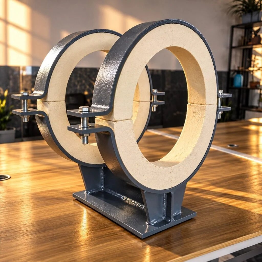
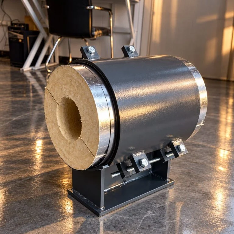
Insulated Pipe Support
An insulated pipe support supports a pipe through an insulating insert and a structural support assembly.
- Insulating insert
- Structural support assembly
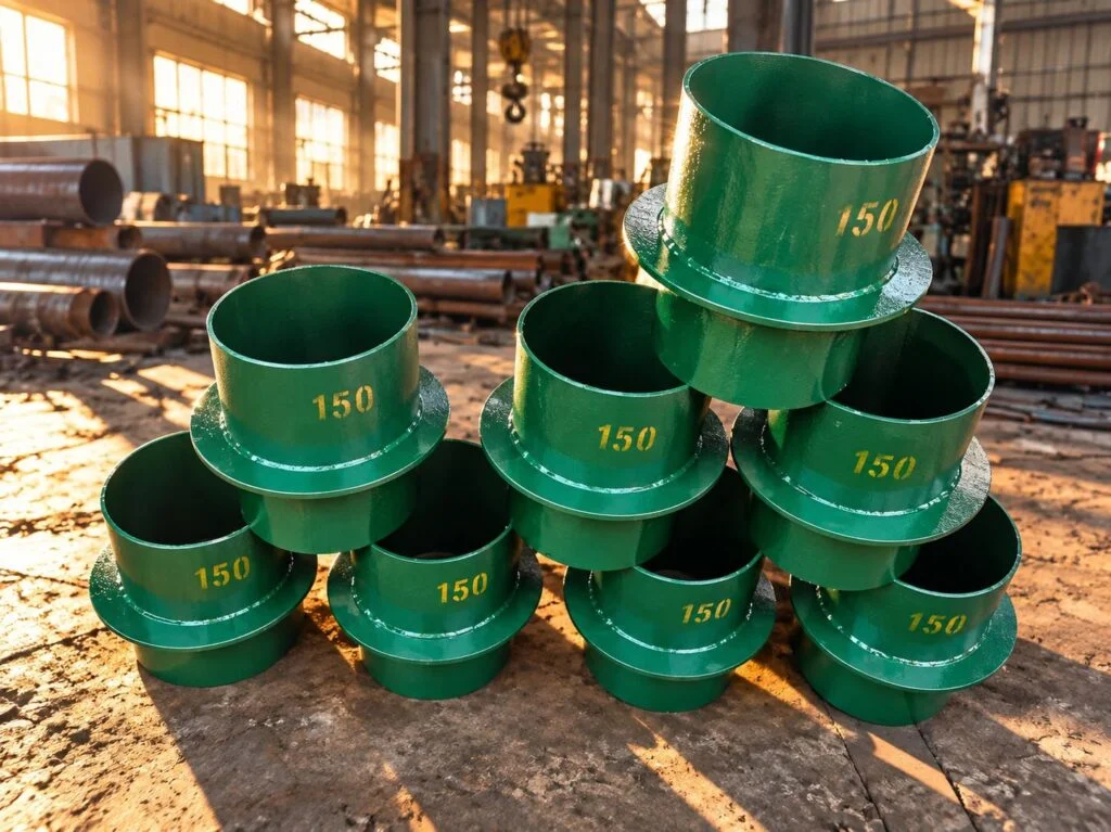
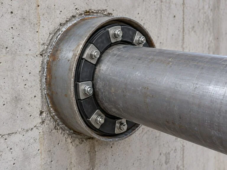
Rigid Wall Sleeve
A rigid wall sleeve creates a defined pipe passage through a wall and can incorporate a puddle flange in the specified concrete penetration detail.
- Wall penetration sleeve
- Puddle-flange option
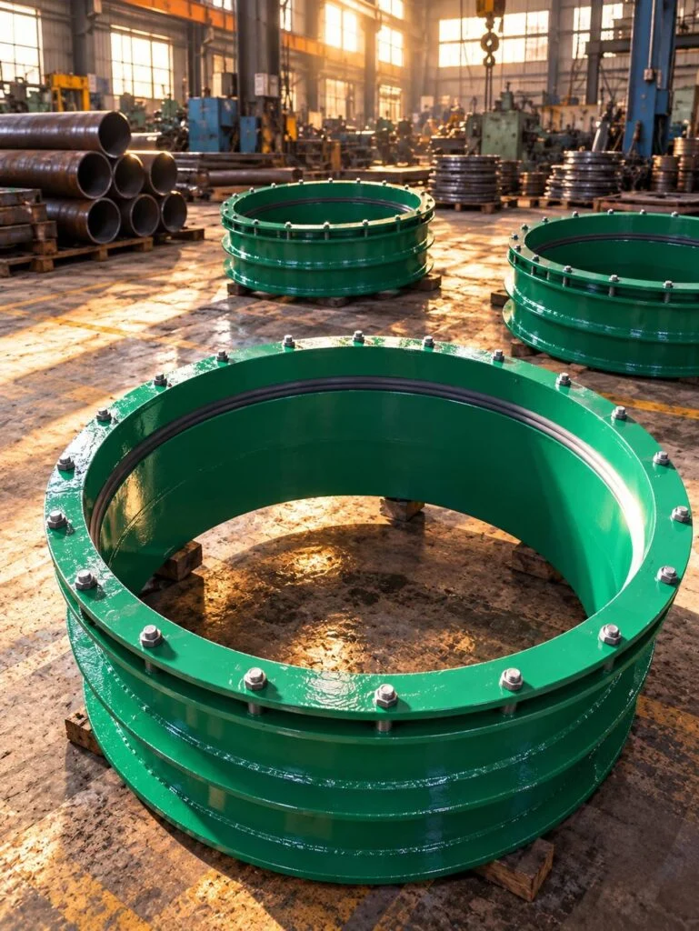
Flexible Waterproof Sleeve
A flexible waterproof sleeve uses a specified housing and sealing assembly around a pipe penetration.
- Bolted gland
- Pipe sealing assembly
Material for the load. Protection for the exposure.
Specify a complete structural or product material grade for plates, sections and sleeves, with thickness and delivery condition. Stainless steel, painted carbon steel and galvanized construction have different corrosion, fabrication and interface considerations. Insulating or sliding inserts require their own temperature and load limits. Confirm the selected materials and available finishes with JINYI.
Specify materials, process and documents for the actual order. Availability is confirmed with quotation.
Specification inputs
Support and casing fabrication schedule
Dimensions and design inputs| Property | What to specify | Reference |
|---|---|---|
| Support duty | Type, tag, loads in kN and movement directions in mm | Designer’s support schedule |
| Pipe interface | Actual OD, wall thickness, liner and insulation allowance | Piping and support drawings |
| Steel assembly | Material grade, plate thickness, weld size and bolt details | Approved fabrication drawing |
| Movement control | Guide gap, travel, stop locations and sliding material | Piping stress design |
| Wall sleeve | Finished ID, length, wall thickness and flange position | Coordinated penetration detail |
| Seal interface | Pipe OD, annular clearance, service medium and water head | Selected seal specification |
| Finish and records | Surface preparation, protection, inspection and tagging | Purchase order and ITP |
Technical references: MSS SP-58 scope, Pipe-support movement guidance, Wall seal selection guide. MSS SP-58 addresses support materials, design, manufacture, selection and installation. Match the project-required edition. Sleeve and seal dimensions must be checked against the selected penetration system, not copied from a nominal pipe size.
Numerical specification examples below explain how to define an enquiry. They are illustrative drawing inputs, not JINYI size, pressure, tolerance or surface-finish guarantees.
| Input | Numerical example | How to specify it |
|---|---|---|
| Annular space | 25 mm radial | Example: a 250 mm sleeve ID around a 200 mm pipe OD gives (250 − 200) ÷ 2 = 25 mm radial space before tolerances. Select the seal to its actual approved range. |
| Guide clearance | 3 mm each side | Illustrative drawing callout: 3 mm on each side gives 6 mm total transverse clearance at the stated installation condition. It does not define axial travel. |
| Support reaction | 12 kN = 12,000 N | Identify the load direction and operating, empty and test cases. This conversion is not a support load rating or an allowable design load. |
Gauging
Methods
Loads, contact geometry, weld dimensions and penetration clearances define the inspection scope.
- Material and thickness
- Weld and baseplate geometry
- Guide gap and movement
- Sleeve ID and flange position
- Tagging and coating records
Define the inspection plan
Documents
Material records, inspection reports and packing list
Measuring equipment
Agree measuring methods, test scope and acceptance criteria for the component.
Drawing-based manufacture
Custom Steel Pipe Support Fabrication
Send the support schedule with load vectors, movement directions, pipe-contact detail and attachment design. Identify which tolerances affect the site connection and which may follow the drawing’s general tolerance note. Slotted holes, adjustable rods and guide gaps must remain functional after welding and coating.
For waterproof casing enquiries, attach the complete wall section and seal detail. A sleeve or puddle flange is only one part of the installation; the seal and wall construction determine the complete water barrier. JINYI will review the fabrication scope, documentation and quotation. Use custom manufacturing and OEM for nonstandard assemblies.
Technical Guide & Buyer QuestionsBefore you order
Practical answers for pipe supports manufacturing. Use these points to prepare a technical enquiry and agree acceptance. These are specification examples and buyer guidance, not customer project or testimonial claims.
Buyer guide What is needed for pipe supports manufacturing? Start from a support schedule Provide pipe OD, support type, material, temperature, load directions, movement and attachment details. Include empty, operating and hydrotest cases when required by the design. Shop fabrication needs a controlled drawing and an agreed acceptance plan, not just a photograph of a similar support.
Buyer guide Can diameter determine a support load rating? Loads need a design basis No. Pipe weight, contents, insulation, span, attachments, thermal movement and temporary conditions affect reactions. State loads and units from the design calculations. A clamp that fits the pipe can still be unsuitable for the intended structural duty.
Buyer guide How is a guide different from an anchor? Define permitted movement A guide normally restricts selected lateral movement while permitting specified travel; an anchor restrains the directions defined by the design. The exact function must be shown on the drawing. Substituting one for the other can change pipe and equipment loads.
 Buyer guide Which tolerances deserve special attention? Focus on installation interfaces
 Identify bolt patterns, baseplate flatness, support height, pipe-contact radius, guide gaps and sleeve bore. Apply tighter tolerances only where they affect function. State datums and the measurement condition so the shop and receiving inspector check the same geometry.
Buyer guide What belongs in a wall sleeve fabrication drawing? Coordinate with the wall section Show pipe OD, sleeve finished ID, wall thickness, sleeve length, puddle-flange position and seal arrangement. Include finished wall surfaces, pipe alignment and fastening access. For cast-in components, confirm how location and orientation are maintained during installation.
Buyer guide How is annular space calculated? Use actual finished dimensions For a concentric circular pipe and sleeve, radial clearance equals (sleeve ID minus pipe OD) divided by two. Coatings, ovality, eccentricity and tolerances reduce available clearance. The calculated value must fit the selected seal system’s permitted dimensions and installation instructions.
Buyer guide Is a waterproof casing a complete seal? Review the full penetration Not by itself. The waterproof pipe casing manufacturing process controls the metal sleeve and its features. Water resistance also depends on wall integration, the seal, workmanship and service conditions. Specify the water head and acceptance criteria for the complete installed detail.
 Buyer guide Can a wall seal carry the pipe? Separate support and sealing duties
 Do not assign structural loads to a seal unless the exact system is documented for that function. Provide suitable independent support and allow the movement required by the piping design. The sleeve, seal and support arrangement must be coordinated.
 Buyer guide What should be checked after galvanizing? Fit can change after finishing
 Review threaded engagement, holes, contact surfaces, guide gaps and seal interfaces. Specify masking, machining allowances or repair methods where required. Confirm the coating inspection scope and any distortion limits before ordering a finish for thin or asymmetric fabrications.
 Buyer guide Are weld inspection requirements always identical? Match the project specification
 No. Visual inspection, NDE methods, extent and acceptance depend on the component and governing requirements. State weld sizes, preparation and any procedure or personnel qualifications. A general statement that a part is welded does not define its acceptance standard.
Buyer guide Can custom supports use standard components? Keep interfaces controlled Standard rods, clamps and fasteners can be incorporated where the design permits them. Confirm their grade, capacity and dimensions, and identify them in the bill of materials. Custom steel pipe support fabrication must preserve the intended load path through every connection.
Buyer guide How should fabricated assemblies be delivered? Tag for the installation sequence Use support tags, orientation marks and a packing list matched to the site schedule. Protect threads and coated surfaces, and retain matched hardware with its assembly. Agree material, dimensional and finish records before production so release is not delayed by missing documents.
Define the load. Coordinate the penetration.
Ready to send your support schedule?
Send support tags, load and movement data, fabrication drawings, material and finish. For sleeves, include pipe OD, wall section and seal details.
Get a quote Confirm the drawing, service conditions and inspection scope before production starts.
JINYI Engineering teamStart here
Start Your Pipe Supports Manufacturing Enquiry
Send support tags, load and movement data, fabrication drawings, material and finish. For sleeves, include pipe OD, wall section and seal details.
JINYI Pipe FittingsCangyan Road Industrial Park · Yanshan County · Cangzhou · Hebei